
Page 396 - Mechanical Engineers' Handbook (Volume 2)
P. 396
2 Control System Structure 387
Figure 6 Block diagram of the position control system shown in Fig. 5. 1
The controller is generally thought of as a logic element that compares the command
with the measurement of the output and decides what should be done. The input and feedback
elements are transducers for converting one type of signal into another type. This allows the
error detector directly to compare two signals of the same type (e.g., two voltages). Not all
functions show up as separate physical elements. The error detector in Fig. 5 is simply the
input terminals of the amplifier.
The control logic elements produce the control signal, which is sent to the final control
elements. These are the devices that develop enough torque, pressure, heat, and so on to
influence the elements under control. Thus, the final control elements are the ‘‘muscle’’ of
the system, while the control logic elements are the ‘‘brain.’’ Here we are primarily concerned
with the design of the logic to be used by this brain.
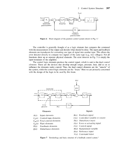
Figure 7 Terminology and basic structure of a feedback control system. 1