
Page 398 - Mechanical Engineers' Handbook (Volume 2)
P. 398
3 Transducers and Error Detectors 389
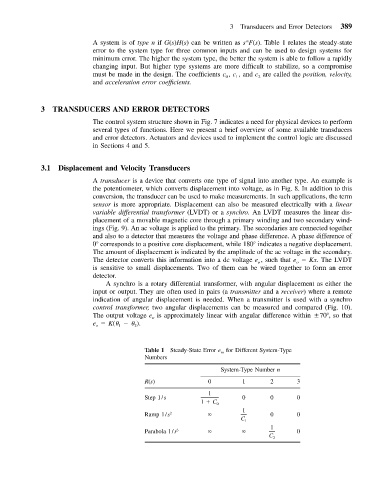
A system is of type n if G(s)H(s) can be written as s F(s). Table 1 relates the steady-state
n
error to the system type for three common inputs and can be used to design systems for
minimum error. The higher the system type, the better the system is able to follow a rapidly
changing input. But higher type systems are more difficult to stabilize, so a compromise
must be made in the design. The coefficients c , c , and c are called the position, velocity,
1
0
2
and acceleration error coefficients.
3 TRANSDUCERS AND ERROR DETECTORS
The control system structure shown in Fig. 7 indicates a need for physical devices to perform
several types of functions. Here we present a brief overview of some available transducers
and error detectors. Actuators and devices used to implement the control logic are discussed
in Sections 4 and 5.
3.1 Displacement and Velocity Transducers
A transducer is a device that converts one type of signal into another type. An example is
the potentiometer, which converts displacement into voltage, as in Fig. 8. In addition to this
conversion, the transducer can be used to make measurements. In such applications, the term
sensor is more appropriate. Displacement can also be measured electrically with a linear
variable differential transformer (LVDT) or a synchro. An LVDT measures the linear dis-
placement of a movable magnetic core through a primary winding and two secondary wind-
ings (Fig. 9). An ac voltage is applied to the primary. The secondaries are connected together
and also to a detector that measures the voltage and phase difference. A phase difference of
0 corresponds to a positive core displacement, while 180 indicates a negative displacement.
The amount of displacement is indicated by the amplitude of the ac voltage in the secondary.
The detector converts this information into a dc voltage e , such that e Kx. The LVDT
o o
is sensitive to small displacements. Two of them can be wired together to form an error
detector.
A synchro is a rotary differential transformer, with angular displacement as either the
input or output. They are often used in pairs (a transmitter and a receiver) where a remote
indication of angular displacement is needed. When a transmitter is used with a synchro
control transformer, two angular displacements can be measured and compared (Fig. 10).
The output voltage e is approximately linear with angular difference within 70 , so that
o
e K( ).
o 1 2
Table 1 Steady-State Error e ss for Different System-Type
Numbers
System-Type Number n
R(s) 0 1 2 3
1
Step 1/s 0 0 0
1 C 0
1
Ramp 1/s 2 0 0
C 1
1
Parabola 1/s 3 0
C 2