
Page 401 - Mechanical Engineers' Handbook (Volume 2)
P. 401
392 Basic Control Systems Design
R can be found from calibration of the device. The pressure drop can be sensed by converting
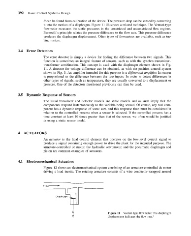
it into the motion of a diaphragm. Figure 11 illustrates a related technique. The Venturi-type
flowmeter measures the static pressures in the constricted and unconstricted flow regions.
Bernoulli’s principle relates the pressure difference to the flow rate. This pressure difference
produces the diaphragm displacement. Other types of flowmeters are available, such as tur-
bine meters.
3.4 Error Detectors
The error detector is simply a device for finding the difference between two signals. This
function is sometimes an integral feature of sensors, such as with the synchro transmitter–
transformer combination. This concept is used with the diaphragm element shown in Fig.
11. A detector for voltage difference can be obtained, as with the position control system
shown in Fig. 5. An amplifier intended for this purpose is a differential amplifier. Its output
is proportional to the difference between the two inputs. In order to detect differences in
other types of signals, such as temperature, they are usually converted to a displacement or
pressure. One of the detectors mentioned previously can then be used.
3.5 Dynamic Response of Sensors
The usual transducer and detector models are static models and as such imply that the
components respond instantaneously to the variable being sensed. Of course, any real com-
ponent has a dynamic response of some sort, and this response time must be considered in
relation to the controlled process when a sensor is selected. If the controlled process has a
time constant at least 10 times greater than that of the sensor, we often would be justified
in using a static sensor model.
4 ACTUATORS
An actuator is the final control element that operates on the low-level control signal to
produce a signal containing enough power to drive the plant for the intended purpose. The
armature-controlled dc motor, the hydraulic servomotor, and the pneumatic diaphragm and
piston are common examples of actuators.
4.1 Electromechanical Actuators
Figure 12 shows an electromechanical system consisting of an armature-controlled dc motor
driving a load inertia. The rotating armature consists of a wire conductor wrapped around
Figure 11 Venturi-type flowmeter. The diaphragm
displacement indicates the flow rate. 1