
Page 404 - Mechanical Engineers' Handbook (Volume 2)
P. 404
4 Actuators 395
Fig. 13 had two lands. If the width of the land is greater than the port width, the valve is
said to be overlapped. In this case, a dead zone exists in which a slight change in the
displacement z produces no power piston motion. Such dead zones create control difficulties
and are avoided by designing the valve to be underlapped (the land width is less the port
width). For such valves there will be a small flow opening even when the valve is in the
neutral position at z 0. This gives it a higher sensitivity than an overlapped valve.
The variables z and p p p determine the volume flow rate, as
1
2
q ƒ(z, p)
For the reference equilibrium condition (z 0, p 0, q 0), a linearization gives
q Cz C p (10)
2
1
5
The linearization constants are available from theoretical and experimental results. The
transfer function for the system is 1,2
X(s) C 1
T(s) (11)
2
Z(s) (Cm/A) s (cC /A A) s Ck/A
2
2
2
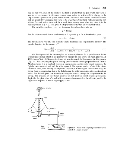
The development of the steam engine led to the requirement for a speed control device
to maintain constant speed in the presence of changes in load torque or steam pressure. In
1788, James Watt of Glasgow developed his now-famous flyball governor for this purpose
(Fig. 14). Watt took the principle of sensing speed with the centrifugal pendulum of Thomas
Mead and used it in a feedback loop on a steam engine. As the motor speed increases, the
flyballs move outward and pull the slider upward. The upward motion of the slider closes
the steam valve, thus causing the engine to slow down. If the engine speed is too slow, the
spring force overcomes that due to the flyballs, and the slider moves down to open the steam
valve. The desired speed can be set by moving the plate to change the compression in the
spring. The principle of the flyball governor is still used for speed control applications.
Typically, the pilot valve of a hydraulic servomotor is connected to the slider to provide the
high forces required to move large supply valves.
Figure 14 James Watt’s flyball governor for speed
control of a steam engine. 1