
Page 409 - Mechanical Engineers' Handbook (Volume 2)
P. 409
400 Basic Control Systems Design
100
K
P
band %
The zero-error valve displacement x is the manual reset.
Proportional Control of a First-Order System
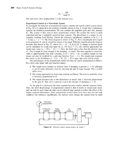
To investigate the behavior of proportional control, consider the speed control system shown
in Fig. 20; it is identical to the position controller shown in Fig. 6, except that a tachometer
replaces the feedback potentiometer. We can combine the amplifier gains into one, denoted
K . The system is thus seen to have proportional control. We assume the motor is field
P
controlled and has a negligible electrical time constant. The disturbance is a torque T , for
d
example, resulting from friction. Choose the reference equilibrium condition to be T T
d
0 and w 0. The block diagram is shown in Fig. 21. For a meaningful error signal
r
to be generated, K and K should be chosen to be equal. With this simplification the diagram
2
1
becomes that shown in Fig. 22, where G(s) K K K K /R. A change in desired speed
T
P
1
can be simulated by a unit step input for .For (s) 1/s, the velocity approaches the
r
r
steady-state value K/(c K) 1. Thus, the final value is less than the desired value
ss
of 1, but it might be close enough if the damping c is small. The time required to reach this
value is approximately four time constants, or 4 4I/(c K). A sudden change in load
torque can also be modeled by a unit step function T (s) 1/s. The steady-state response
d
due solely to the disturbance is 1/(c K). If c K is large, this error will be small.
The performance of the proportional control law thus far can be summarized as follows.
For a first-order plant with step function inputs:
1. The output never reaches its desired value if damping is present (c 0), although
it can be made arbitrarily close by choosing the gain K large enough. This is called
offset error.
2. The output approaches its final value without oscillation. The time to reach this value
is inversely proportional to K.
3. The output deviation due to the disturbance at steady state is inversely proportional
to the gain K. This error is present even in the absence of damping (c 0).
As the gain K is increased, the time constant becomes smaller and the response faster.
Thus, the chief disadvantage of proportional control is that it results in steady-state errors
and can only be used when the gain can be selected large enough to reduce the effect of the
largest expected disturbance. Since proportional control gives zero error only for one load
condition (the reference equilibrium), the operator must change the manual reset by hand
Figure 20 Velocity control system using a dc motor. 1