
Page 405 - Mechanical Engineers' Handbook (Volume 2)
P. 405
396 Basic Control Systems Design
Many hydraulic servomotors use multistage valves to obtain finer control and higher
forces. A two-stage valve has a slave valve, similar to the pilot valve but situated between
the pilot valve and the power piston.
Rotational motion can be obtained with a hydraulic motor, which is, in principle, a
pump acting in reverse (fluid input and mechanical rotation output). Such motors can achieve
higher torque levels than electric motors. A hydraulic pump driving a hydraulic motor con-
stitutes a hydraulic transmission.
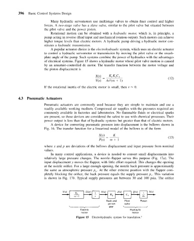
A popular actuator choice is the electrohydraulic system, which uses an electric actuator
to control a hydraulic servomotor or transmission by moving the pilot valve or the swash-
plate angle of the pump. Such systems combine the power of hydraulics with the advantages
of electrical systems. Figure 15 shows a hydraulic motor whose pilot valve motion is caused
by an armature-controlled dc motor. The transfer function between the motor voltage and
the piston displacement is
X(s) KK C 1
2
1
(12)
2
V(s) As ( s 1)
If the rotational inertia of the electric motor is small, then 0.
4.3 Pneumatic Actuators
Pneumatic actuators are commonly used because they are simple to maintain and use a
readily available working medium. Compressed air supplies with the pressures required are
commonly available in factories and laboratories. No flammable fluids or electrical sparks
are present, so these devices are considered the safest to use with chemical processes. Their
power output is less than that of hydraulic systems but greater than that of electric motors.
A device for converting pneumatic pressure into displacement is the bellows shown in
Fig. 16. The transfer function for a linearized model of the bellows is of the form
X(s) K
(13)
P(s) s 1
where x and p are deviations of the bellows displacement and input pressure from nominal
values.
In many control applications, a device is needed to convert small displacements into
relatively large pressure changes. The nozzle–flapper serves this purpose (Fig. 17a). The
input displacement y moves the flapper, with little effort required. This changes the opening
at the nozzle orifice. For a large enough opening, the nozzle back pressure is approximately
the same as atmospheric pressure p . At the other extreme position with the flapper com-
a
pletely blocking the orifice, the back pressure equals the supply pressure p . This variation
s
is shown in Fig. 17b. Typical supply pressures are between 30 and 100 psia. The orifice
Figure 15 Electrohydraulic system for translation. 1