
Page 403 - Mechanical Engineers' Handbook (Volume 2)
P. 403
394 Basic Control Systems Design
(s) K T
(9)
V(s) (Ls R)(Is c)
where R and L are the resistance and inductance of the field circuit and K is the torque
T
constant. No back emf exists in this motor to act as a self-braking mechanism.
Two-phase ac motors can be used to provide a low-power, variable-speed actuator. This
motor type can accept the ac signals directly from LVDTs and synchros without demodu-
lation. However, it is difficult to design ac amplifier circuitry to do other than proportional
action. For this reason, the ac motor is not found in control systems as often as dc motors.
The transfer function for this type is of the form of Eq. (9).
An actuator especially suitable for digital systems is the stepper motor, a special dc
motor that takes a train of electrical input pulses and converts each pulse into an angular
displacement of a fixed amount. Motors are available with resolutions ranging from about 4
steps per revolution to more than 800 steps per revolution. For 36 steps per revolution, the
motor will rotate by 10 for each pulse received. When not being pulsed, the motors lock
in place. Thus, they are excellent for precise positioning applications, such as required with
printers and computer tape drives. A disadvantage is that they are low-torque devices. If the
input pulse frequency is not near the resonant frequency of the motor, we can take the output
rotation to be directly related to the number of input pulses and use that description as the
motor model.
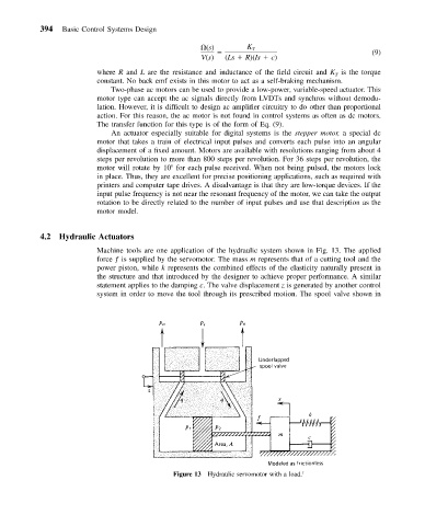
4.2 Hydraulic Actuators
Machine tools are one application of the hydraulic system shown in Fig. 13. The applied
force ƒ is supplied by the servomotor. The mass m represents that of a cutting tool and the
power piston, while k represents the combined effects of the elasticity naturally present in
the structure and that introduced by the designer to achieve proper performance. A similar
statement applies to the damping c. The valve displacement z is generated by another control
system in order to move the tool through its prescribed motion. The spool valve shown in
Figure 13 Hydraulic servomotor with a load. 1