
Page 402 - Mechanical Engineers' Handbook (Volume 2)
P. 402
4 Actuators 393
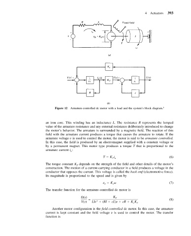
Figure 12 Armature-controlled dc motor with a load and the system’s block diagram. 1
an iron core. This winding has an inductance L. The resistance R represents the lumped
value of the armature resistance and any external resistance deliberately introduced to change
the motor’s behavior. The armature is surrounded by a magnetic field. The reaction of this
field with the armature current produces a torque that causes the armature to rotate. If the
armature voltage v is used to control the motor, the motor is said to be armature controlled.
In this case, the field is produced by an electromagnet supplied with a constant voltage or
by a permanent magnet. This motor type produces a torque T that is proportional to the
armature current i :
a
T Ki (6)
Ta
The torque constant K depends on the strength of the field and other details of the motor’s
T
construction. The motion of a current-carrying conductor in a field produces a voltage in the
conductor that opposes the current. This voltage is called the back emf (electromotive force).
Its magnitude is proportional to the speed and is given by
e K (7)
e
b
The transfer function for the armature-controlled dc motor is
(s) K T (8)
2
V(s) LIs (RI cL)s cR KK T
e
Another motor configuration is the field-controlled dc motor. In this case, the armature
current is kept constant and the field voltage v is used to control the motor. The transfer
function is