
Page 406 - Mechanical Engineers' Handbook (Volume 2)
P. 406
4 Actuators 397
Figure 16 Pneumatic bellows. 1
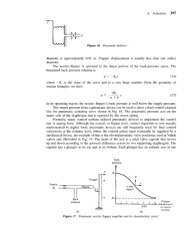
diameter is approximately 0.01 in. Flapper displacement is usually less than one orifice
diameter.
The nozzle–flapper is operated in the linear portion of the back-pressure curve. The
linearized back pressure relation is
p Kx (14)
ƒ
where K is the slope of the curve and is a very large number. From the geometry of
ƒ
similar triangles, we have
aK ƒ
p y (15)
a b
In its operating region, the nozzle–flapper’s back pressure is well below the supply pressure.
The output pressure from a pneumatic device can be used to drive a final control element
like the pneumatic actuating valve shown in Fig. 18. The pneumatic pressure acts on the
upper side of the diaphragm and is opposed by the return spring.
Formerly, many control systems utilized pneumatic devices to implement the control
law in analog form. Although the overall, or higher level, control algorithm is now usually
implemented in digital form, pneumatic devices are still frequently used for final control
corrections at the actuator level, where the control action must eventually be supplied by a
mechanical device. An example of this is the electropneumatic valve positioner used in Valtek
valves and illustrated in Fig. 19. The heart of the unit is a pilot valve capsule that moves
up and down according to the pressure difference across its two supporting diaphragms. The
capsule has a plunger at its top and at its bottom. Each plunger has an exhaust seat at one
Figure 17 Pneumatic nozzle–flapper amplifier and its characteristic curve. 1