
Page 407 - Mechanical Engineers' Handbook (Volume 2)
P. 407
398 Basic Control Systems Design
Figure 18 Pneumatic flow control valve. 1
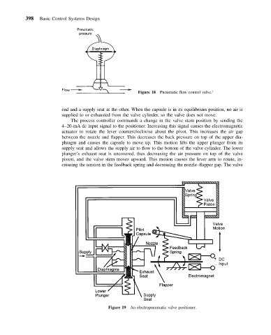
end and a supply seat at the other. When the capsule is in its equilibrium position, no air is
supplied to or exhausted from the valve cylinder, so the valve does not move.
The process controller commands a change in the valve stem position by sending the
4–20-mA dc input signal to the positioner. Increasing this signal causes the electromagnetic
actuator to rotate the lever counterclockwise about the pivot. This increases the air gap
between the nozzle and flapper. This decreases the back pressure on top of the upper dia-
phragm and causes the capsule to move up. This motion lifts the upper plunger from its
supply seat and allows the supply air to flow to the bottom of the valve cylinder. The lower
plunger’s exhaust seat is uncovered, thus decreasing the air pressure on top of the valve
piston, and the valve stem moves upward. This motion causes the lever arm to rotate, in-
creasing the tension in the feedback spring and decreasing the nozzle–flapper gap. The valve
Figure 19 An electropneumatic valve positioner.