
Page 394 - Mechanical Engineers' Handbook (Volume 2)
P. 394
1 Introduction 385
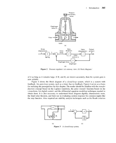
Figure 2 Pressure regulator: (a) cutaway view; (b) block diagram. 1
of A as long as A remains large. If R and R are known accurately, then the system gain is
1
2
now reliable.
Figure 4 shows the block diagram of a closed-loop system, which is a system with
feedback. An open-loop system, such as a timer, has no feedback. Figure 4 serves as a focus
for outlining the prerequisites for this chapter. The reader should be familiar with the transfer
function concept based on the Laplace transform, the pulse transfer function based on the
z-transform, for digital control, and the differential equation modeling techniques needed to
obtain them. It is also necessary to understand block diagram algebra, characteristic roots,
the final-value theorem, and their use in evaluating system response for common inputs like
the step function. Also required are stability analysis techniques such as the Routh criterion
Figure 3 A closed-loop system.