
Page 477 - Mechanical Engineers' Handbook (Volume 2)
P. 477
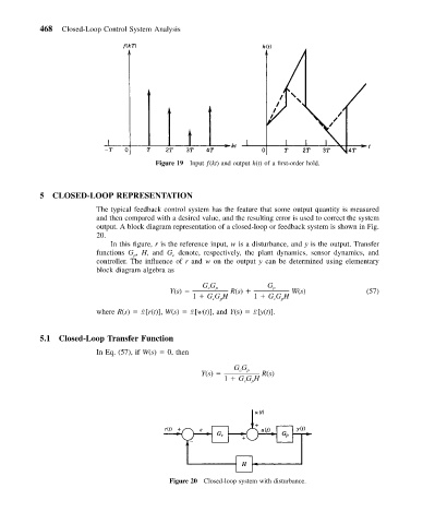
468   Closed-Loop Control System Analysis


                                         Figure 19 Input ƒ(kt) and output h(t) of a first-order hold.


           5  CLOSED-LOOP REPRESENTATION
                          The typical feedback control system has the feature that some output quantity is measured
                          and then compared with a desired value, and the resulting error is used to correct the system
                          output. A block diagram representation of a closed-loop or feedback system is shown in Fig.
                          20.
                             In this figure, r is the reference input, w is a disturbance, and y is the output. Transfer
                          functions G , H, and G denote, respectively, the plant dynamics, sensor dynamics, and
                                   p
                                             c
                          controller. The influence of r and w on the output y can be determined using elementary
                          block diagram algebra as
                                                     GG p            G p
                                                      c
                                            Y(s)            R(s)           W(s)               (57)
                                                  1   GG H        1   GG H
                                                       c  p            c  p
                          where R(s)   L[r(t)], W(s)   L[w(t)], and Y(s)   L[y(t)].

           5.1  Closed-Loop Transfer Function

                          In Eq. (57), if W(s)   0, then
                                                             GG
                                                    Y(s)      c  p  R(s)
                                                          1   GG H
                                                                 p
                                                               c


                                            Figure 20 Closed-loop system with disturbance.