
Page 491 - Mechanical Engineers' Handbook (Volume 2)
P. 491
482 Closed-Loop Control System Analysis
Figure 29 Nyquist contour and its mapping by GH(s).
1
GH(s)
s(s 1)
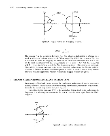
The contour in the s-plane is shown in Fig. 31a, where an indentation is affected by a
small semicircle of radius
, where
0. When mapped by GH(s), the contour of Fig. 31b
is obtained. To effect the mapping, the points on the semicircles are represented as s
e j
j
on the small indentation with
[
/2,
/2] and
→ 0 and s Re with
[
/2,
/2]
and R → on the infinite semicircle. We observe that the ( 1,0) point is not encircled.
Since GH(s) does not have any poles in the right-half s-plane from the Nyquist stability
criterion, it follows that the closed-loop system is stable. In Table 3 several loop transfer
functions with the appropriate Nyquist contour and mapped contours are given.
7 STEADY-STATE PERFORMANCE AND SYSTEM TYPE
In the design of feedback control systems the steady-state performance is also of importance
in many instances. This is in addition to the stability and transient performance requirements.
Consider the closed-loop system shown in Fig. 32.
Here G (s) is the plant and G (s) is the controller. When steady-state performance is
c
p
important, it is advantageous to consider the system error due to an input. From the block
diagram
Figure 30 Nyquist contour with indentations.