
Page 503 - Mechanical Engineers' Handbook (Volume 2)
P. 503
494 Closed-Loop Control System Analysis
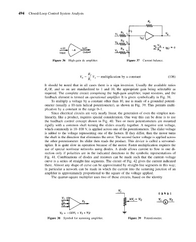
Figure 36 High-gain dc amplifier. Figure 37 Current balance.
R ƒ
V V multiplication by a constant (106)
0
1
R 1
It should be noted that in all cases there is a sign inversion. Usually the available ratios
R /R and so on are standardized to 1 and 10, the appropriate gain being selectable as
1
ƒ
required. The complete circuit comprising the high-gain amplifier, input resistors, and the
feedback element is termed an operational amplifier. It is given symbolically in Fig. 38.
To multiply a voltage by a constant other than 10, use is made of a grounded potenti-
ometer (usually a 10-turn helical potentiometer), as shown in Fig. 39. This permits multi-
plication by a constant in the range 0–1.
Since electrical circuits are very nearly linear, the generation of even the simplest non-
linearity, like a product, requires special consideration. One way this can be done is to use
the feedback control concept shown in Fig. 40. Two or more potentiometers are mounted
rigidly with a common shaft turning the sliders exactly together. A negative unit voltage,
which commonly is 10–100 V, is applied across one of the potentiometers. The slider voltage
is added to the voltage representing one of the factors. If they differ, then the motor turns
the shaft in the direction that eliminates the error. The second factor voltage is applied across
the other potentiometer. Its slider then reads the product. This device is called a servomul-
tiplier. It is quite slow in operation because of the motor. Faster multiplication requires the
use of special nonlinear networks using diodes. A diode allows current to flow in one di-
rection only if polarities are in the indicated directions in the symbolic representations of
Fig. 41. Combinations of diodes and resistors can be made such that the current–voltage
curve is a series of straight-line segments. The circuit of Fig. 42 gives the current indicated
there. Almost any shape of curve can be approximated by straight-line segments in this way;
in particular a network can be made in which the current into the summing junction of an
amplifier is approximately proportional to the square of the voltage applied.
The quarter-square multiplier uses two of these circuits, based on the identity
Figure 38 Symbol for summing amplifier. Figure 39 Potentiometer.