
Page 504 - Mechanical Engineers' Handbook (Volume 2)
P. 504
8 Simulation for Control System Analysis 495
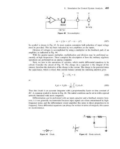
Figure 40 Servomultiplier.
2
2
xy 1 – [(x y) (x y) ] (107)
4
Its symbol is shown in Fig. 43. In most modern computers both polarities of input voltage
must be provided. This has been indicated by two amplifiers on the inputs.
Division of voltages is accomplished by using a multiplier in the feedback path of an
amplifier, as indicated in Fig. 44.
With the quarter-square multiplier, multiplication and division may be performed ac-
curately at high frequencies. These complete the description of how the ordinary algebraic
operations are performed on an analog computer.
Next, we turn to the operations of calculus, which enable differential equations to be
solved. Consider the circuit of Fig. 45. The charge on a capacitor is the integral of the
current; therefore the derivative of the charge is the current. The charge is the potential times
the capacitance, which is fixed; thus current balance around the summing junction gives
V
˙
1 CV 0 (108)
R 2
or
1 t
V (t) V (0) V ( ) d (109)
1
0
2
RC 0
Thus this circuit is an accurate integrator with a proportionality factor or time constant of
RC. A common symbol is shown in Fig. 46. The initial condition can be set in with a special
network furnished with most computers.
Differentiation can be performed with an input capacitor and a feedback resistor; how-
ever, it is not generally recommended because input signals are often contaminated by high-
frequency noise, and the differentiator circuit amplifies this noise in direct proportion to its
frequency. Since differential equations can always be written in terms of integrals, this causes
no inconvenience.
Figure 41 Diode. Figure 42 Diode network.