
Page 508 - Mechanical Engineers' Handbook (Volume 2)
P. 508
8 Simulation for Control System Analysis 499
Figure 51 Rectifier.
atively limited accuracy and repeatability due in part to amplifier drift. As a consequence of
the very rapid development of digital computer hardware and software giving ever greater
capability and flexibility at reducing cost, system simulation is inevitably being carried out
more and more on the digital computer. There is effectively no problem of overloading,
enabling wide ranges of parameter variation to be accommodated.
The solution of a differential equation involves the process of integration, and for the
digital computer analytical integration must be replaced by some numerical method that
yields an approximation to the true solution. A number of special programming languages
referred to as continuous system simulation languages (CSSLs) or simply as simulation
languages are available as analytical tools to study the dynamic behavior of a wide range of
systems without the need for a detailed knowledge of computing procedures. The languages
are designed to be simple to understand and use, and they minimize programming difficulty
by allowing the program to be written as a sequence of relatively self-descriptive statements.
Numerous different languages with acronyms such as ACSL, CSMP, CSSL, DYNAMO,
DARE, MIMIC, TELSIM, ENPORT, SCEPTRE, and SIMNON have been developed by
computer manufacturers, software companies, universities, and others, some for specific fam-
ilies of machines and others for wider applications. Due to standardization, a number of the
languages tend to be broadly similar. Symbolic names are used for the system variables, and
the main body of the program is written as a series of simple statements based on the system
state equations, block diagrams, or bond graphs. To these are added statements specifying
initial parameter values and values of system constants and simple command statements
controlling the running of the program and specifying the form in which the output is
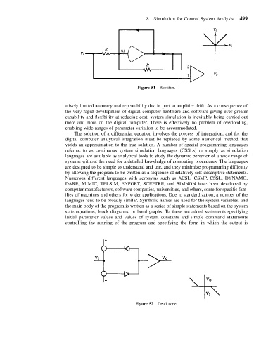
Figure 52 Dead zone.