Page 541 - Mechanical Engineers' Handbook (Volume 2)
P. 541
532   Control System Performance Modification
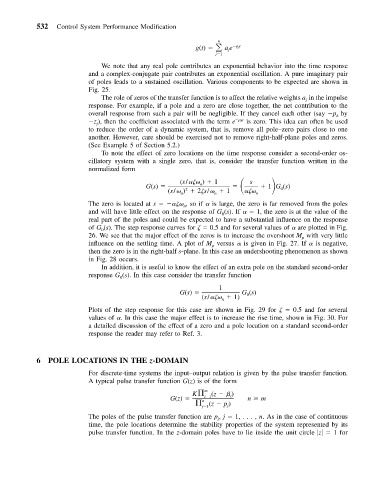
                                                       g(t)      ae  pt j
                                                              n
                                                             j 1  j
                             We note that any real pole contributes an exponential behavior into the time response
                          and a complex-conjugate pair contributes an exponential oscillation. A pure imaginary pair
                          of poles leads to a sustained oscillation. Various components to be expected are shown in
                          Fig. 25.
                             The role of zeros of the transfer function is to affect the relative weights a in the impulse
                                                                                      j
                          response. For example, if a pole and a zero are close together, the net contribution to the
                          overall response from such a pair will be negligible. If they cancel each other (say  p by
                                                                                              k
                           z ), then the coefficient associated with the term e  pt k  is zero. This idea can often be used
                            j
                          to reduce the order of a dynamic system, that is, remove all pole–zero pairs close to one
                          another. However, care should be exercised not to remove right-half-plane poles and zeros.
                          (See Example 5 of Section 5.2.)
                             To note the effect of zero locations on the time response consider a second-order os-
                          cillatory system with a single zero, that is, consider the transfer function written in the
                          normalized form
                                                   (s/
  )   1       s    1 G (s)
                                          G(s)           n
                                                (s/  )   2
s/    1
  n     0
                                                     2
                                                             n
                                                   n
                          The zero is located at s
  ,soif   is large, the zero is far removed from the poles
                                                    n
                          and will have little effect on the response of G (s). If     1, the zero is at the value of the
                                                               0
                          real part of the poles and could be expected to have a substantial influence on the response
                          of G (s). The step response curves for
   0.5 and for several values of   are plotted in Fig.
                             0
                          26. We see that the major effect of the zeros is to increase the overshoot M with very little
                                                                                     p
                          influence on the settling time. A plot of M versus   is given in Fig. 27. If   is negative,
                                                            p
                          then the zero is in the right-half s-plane. In this case an undershooting phenomenon as shown
                          in Fig. 28 occurs.
                             In addition, it is useful to know the effect of an extra pole on the standard second-order
                          response G (s). In this case consider the transfer function
                                  0
                                                              1
                                                   G(s)             G (s)
                                                         (s/
    1)  0
                                                               n
                          Plots of the step response for this case are shown in Fig. 29 for
   0.5 and for several
                          values of  . In this case the major effect is to increase the rise time, shown in Fig. 30. For
                          a detailed discussion of the effect of a zero and a pole location on a standard second-order
                          response the reader may refer to Ref. 3.
           6  POLE LOCATIONS IN THE z-DOMAIN
                          For discrete-time systems the input–output relation is given by the pulse transfer function.
                          A typical pulse transfer function G(z) is of the form
                                                      K	  m  (z     )
                                                G(z)      i 1    i    n   m
                                                       	 n  (z   p )
                                                         j 1    j
                          The poles of the pulse transfer function are p , j   1,..., n. As in the case of continuous
                                                              j
                          time, the pole locations determine the stability properties of the system represented by its
                          pulse transfer function. In the z-domain poles have to lie inside the unit circle  z    1 for

