
Page 60 - Mechanical Engineers' Handbook (Volume 2)
P. 60
4 Operating Point of Static Systems 49
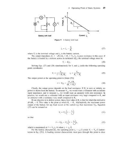
Figure 9 A battery with load.
V
i i t (27)
b
sc
R o
where V is the terminal voltage and i is the battery current.
t
b
The output impedance Z dV /di R V /i (a pure resistance in this case). If
t
b
o
oc
sc
o
the battery is loaded by a resistor across its terminals (R ), the terminal voltage must be
L
V Ri (28)
L b
t
Solving Eqs. (27) and (28) simultaneously for V and i yields the following operating
b
t
point coordinates:
V V
V oc i oc (29)
t
b
1 R /R L R R L
o
o
The output power at the operating point is [from (29)]
2
(V ) R
P Vi oc L (30)
tb
(R R ) 2
o
L
Clearly, the output power depends on the load resistance. If R is zero or infinite, no
L
power is drawn from the battery. To measure V , we would want a voltmeter with an infinite
oc
input impedance, and to measure i , we would want an ammeter with zero resistance. In
sc
practice, we would use a voltmeter with an input resistance very large compared to R and
o
an ammeter with a resistance very small compared to R .
o
If our objective is to deliver power, then a best value of R is that for which the derivative
L
dP/dR 0. This value is the point at which R R . Alternatively, the maximum power
L
o
L
output of the battery for any load occurs at the current (i ) that maximizes V i . Equation
t b
b
(27) can be restated as
V V
i
b
1
oc
t
i (31)
sc
so that
i
1 b i (32)
P Vi V b
oc
tb
i sc
which is maximized at P V i /4 when i i /2.
sc
oc sc
b
For the battery characteristic, the operating point i i /2 yields V V /2 [substi-
oc
b
sc
t
tution in Eq. (29)]. A loading resistor characteristic must pass through this point to draw