Page 64 - Mechanical Engineers' Handbook (Volume 2)
P. 64

4 Operating Point of Static Systems  53


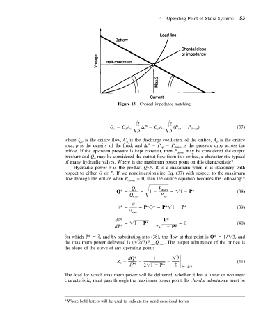
                                                Figure 13 Chordal impedance matching.


                                                        2            2
                                             Q   CA       P   CA      (P    P   )               (37)
                                                   d
                                                     o
                                              o
                                                        
       d  o    
  up  down
                           where Q is the orifice flow, C is the discharge coefficient of the orifice, A is the orifice
                                  o
                                                   d
                                                                                       o
                           area, 
 is the density of the fluid, and  P   P up    P down  is the pressure drop across the
                           orifice. If the upstream pressure is kept constant, then P down  may be considered the output
                           pressure and Q may be considered the output flow from this orifice, a characteristic typical
                                       o
                           of many hydraulic valves. Where is the maximum power point on this characteristic?
                              Hydraulic power P is the product Q P. It is a maximum when it is stationary with
                           respect to either Q or P. If we nondimensionalize Eq. (37) with respect to the maximum
                           flow through the orifice when P down    0, then the orifice equation becomes the following:*
                                                      Q         P
                                                Q*     o      1    down     1   P*              (38)
                                                     Q max       P up
                                                      P
                                                P*        P*Q*   P* 1   P*                      (39)
                                                     P max
                                               dP*                P*
                                                      1   P*              0                     (40)
                                               dP*             2 1   P*
                           for which P*   –,  and by substitution into (38), the flow at that point is Q*   1/ 3,  and
                                        2
                                        3
                           the maximum power delivered is ( 2/3) P max Q max . The output admittance of the orifice is
                           the slope of the curve at any operating point:
                                                                       3
                                                    dQ*       1
                                                Z                                               (41)
                                                 o
                                                    dP*   2 1   P*     2  P* 2/3
                           The load for which maximum power will be delivered, whether it has a linear or nonlinear
                           characteristic, must pass through the maximum power point. Its chordal admittance must be


                           *Where bold letters will be used to indicate the nondimensional forms.
   59   60   61   62   63   64   65   66   67   68   69