
Page 63 - Mechanical Engineers' Handbook (Volume 2)
P. 63
52 Input and Output Characteristics
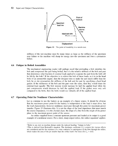
Figure 12 The point of instability in a tensile test.
stiffness of the test machine must be many times as large as the stiffness of the specimen
near failure or the machine will dump its energy into the specimen and force a premature
failure.
4.6 Fatigue in Bolted Assemblies
The mechanical engineering reader will perhaps recall that preloading a bolt stretches the
bolt and compresses the part being bolted, but it is the relative stiffness of the bolt and part
that determines what fraction of external loads applied to separate the part from the bolt will
be felt by the bolt.* If the objective is to relieve the bolt of these loads, as it is in the head
bolts of an automobile engine, then the designer tries to make the part much stiffer than the
bolt; he or she mismatches the stiffness of the bolt and the part by specifying a hard head
gasket. If the stiffnesses of the bolt and the part were the same, then they would share the
external load equally: The bolt tension would increase by half the applied load while the
part compression would decrease by half the applied load. If the gasket were very soft
compared to the bolts, then the bolts would see virtually all of the applied load.
4.7 Operating Point for Nonlinear Characteristics
Let us continue to use the battery as an example of a linear source. It should be obvious
that the maximum power point for the battery is independent of the load it must drive, but
the load characteristic, however nonlinear, must pass through this point for maximum power
transfer. Figure 13 illustrates this. It is not the slope of the load impedance that must match
the source impedance, it is the chordal slope, the slope of a line from the origin of the power
plane to the maximum power point of the source.
An orifice supplied from a constant upstream pressure and loaded at its output is a good
example of a nonlinear source. For a short, sharp-edged orifice, the orifice equation† applies:
*Refer to any text on machine design under the indexed heading ‘‘fatigue in bolts.’’
†This is derived from Bernoulli’s equation. The discharge coefficient (C d ) corrects for viscous effects
not considered and for the existence of a vena contracta or convergence in the flow through the orifice,
which makes the area of the jet smaller than the orifice itself. For most oils C d 0.62.