Page 65 - Mechanical Engineers' Handbook (Volume 2)
P. 65

54   Input and Output Characteristics

                                                          Q*   1/ 3    3
                                                           op
                                                  Z chordal                                   (42)
                                                          P*    2/3    2
                                                           op
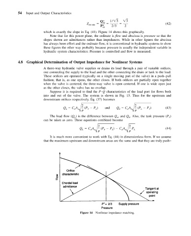
                          which is exactly the slope in Eq. (41). Figure 14 shows this graphically.
                             Note that for this power plane, the ordinate is flow and abscissa is pressure so that the
                          slopes shown are admittances rather than impedances. While in other figures the abscissa
                          has always been effort and the ordinate flow, it is conventional in hydraulic systems to show
                          these figures the other way probably because pressure is usually the independent variable in
                          hydraulic system characteristics: Pressure is controlled and flow is measured.

           4.8  Graphical Determination of Output Impedance for Nonlinear Systems

                          A three-way hydraulic valve supplies or drains its load through a pair of variable orifices,
                          one connecting the supply to the load and the other connecting the drain or tank to the load.
                          These orifices are operated (typically on a single moving part of the valve) in a push–pull
                          fashion; that is, as one opens, the other closes. If both orifices are partially open together
                          when the valve is centered, the three-way valve is open centered. If one is wide open just
                          as the other closes, the valve has no overlap.
                             Suppose it is required to find the P–Q characteristics of the load port for flows both
                          into and out of the valve. The system is shown in Fig. 15. Thus for the upstream and
                          downstream orifices respectively, Eq. (37) becomes
                                               2                             2
                                     Q   CA  u   
 (P   P )  and   Q   CA  d   
  (P   P )    (43)
                                                       L
                                                  S
                                                                         d
                                                                    d
                                                                                     T
                                                                                L
                                           d
                                      u
                             The load flow (Q ) is the difference between Q , and Q . Also, the tank pressure (P )
                                                                   u
                                           L
                                                                                                T
                                                                          d
                          can be taken as zero. These equations combined become
                                                        2                 2
                                              Q   CA      (P   P )   CA    P                  (44)
                                                    d
                                                      u
                                               L
                                                         
  S   L     d  d   
  L
                             It is much more convenient to work with Eq. (44) in dimensionless form. If we assume
                          that the maximum upstream and downstream areas are the same and that they are truly push–


                                              Figure 14 Nonlinear impedance matching.
   60   61   62   63   64   65   66   67   68   69   70