
Page 70 - Mechanical Engineers' Handbook (Volume 2)
P. 70
5 Transforming the Operating Point 59
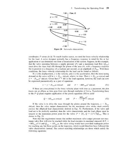
Figure 20 Servovalve characteristic.
coordinates: F versus dv/dt. To match load to source, we need the force–velocity relationship
for the load. A servo designer normally has a frequency response in mind for his or her
application or can determine one from a linearization of the system. Suppose, in this example,
that the valve operating between a supply pressure (P ) and a maximum load flow (Q max )
s
must drive the mass load (M) through the piston of the area (A), with a frequency response
flat in position to a frequency of (radians per second), at an amplitude of D max . With these
conditions, the force–velocity relationship for the load can be found as follows.
If y is the displacement, ˙y is the velocity, and ¨y is the acceleration, then the most taxing
demand on the servo will be y D max sin( t), where t is time. Then ˙y D max cos( t) and
¨ y D max sin( t). Given that F M¨y is the load equation, however, the load can now
2
be expressed parametrically as a pair of equations:
v ˙y D max cos( t) and F MD max sin( t) (51)
2
If these are cross-plotted in the force–velocity plane with time as a parameter, the plot
traces out an ellipse as time goes from zero through multiples of 2 / . Transforming these
to the P–Q plane requires application of the piston equations (50) to yield
MD 2
Q AD max cos( t) and P max sin( t) (52)
A
If the valve is to drive the mass through the piston around the trajectory, y D
max
sin( t), then the valve output characteristic for the maximum valve stroke must entirely
enclose the elliptical load characteristic derived in Eqs. 52. Furthermore, if the valve and
load are to be perfectly matched, then the valve characteristic and the load ellipse must be
tangent at the maximum power point for the valve: P P , Q (1/ 3) Q max . This is
2
–
S
3
shown in Fig. 21.
Note that this requirement means that neither maximum valve output pressure nor max-
imum valve flow will ever be reached while the load executes its maximal sinusoid. If P
s
MD max /A and Q max AD max , the valve sizing would have provided inadequate power
2
for reaching any but those points on the trajectory, which would therefore have followed the
valve characteristic instead. The correct matching relationships are those which satisfy the
following equations: