
Page 72 - Mechanical Engineers' Handbook (Volume 2)
P. 72
6 Measurement Systems 61
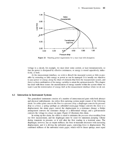
Figure 22 Matching power requirements for a mass load with dissipation.
voltage in a circuit, for example, we must draw some current, at least instantaneously, so
that the power is dissipated by effective resistances, or energy is stored capacitively, induc-
tively, or both.
At the measurement interface, we wish to disturb the measured system as little as pos-
sible by extracting as little energy or power as can be managed. It is usually our objective
to pass power or energy along the chain of elements that form the measurement system, and
there is a best combination of the energy variables to attain the optimum transfer. This chapter
has dealt with these issues: the maximization of energy transfer within the system where we
want it and the minimization of energy theft at the measurement interface where we do not.
6.1 Interaction in Instrument Systems
The generalized instrument consists of a number of interconnected parts with both abstract
and physical embodiments. An orifice flow-metering system might consist of the following
chain: An orifice plate converts the flow to a pressure drop; a diaphragm converts the pressure
drop to a force; a spring (perhaps an unbonded strain-gage bridge) converts the force to a
displacement; the strain gages convert the displacement to a resistance change; a bridge
arrangement converts the resistance change to a differential voltage; and a galvanometer
converts the voltage to a trace on paper. Figure 23 illustrates this chain.
In setting up this chain, the orifice is sized to minimize the pressure drop resulting from
our flow measurement, and the diaphragm must be sized for minimum pumping volume
during transients in pressure, or it will alter the flow reading in a transient sense. The
diaphragm, however, has an output stiffness; the force it transmits decreases with increasing
displacement, and it is driving the unbonded gages, converting force to displacement. The
combined stiffness of the unbonded strain gages, which will be linear springs, must equal