
Page 71 - Mechanical Engineers' Handbook (Volume 2)
P. 71
60 Input and Output Characteristics
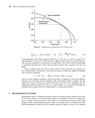
Figure 21 Matching power requirements for a dynamic load.
1 2 MD max 2
Q max AD max cos( t) and P sin( t) (53)
s
3 3 A
, , M, Q , P , and A,soany fiveof
at the appropriate time. These equations relate D max
max s
these determine t and the sixth. If the load mass, supply pressure, piston area, peak frequency,
and maximum amplitude are all known, for example, Eqs. (53) size the valve by determining
its maximum required flow. If the valve has been selected, these equations will size the
piston.
In the example above, the load was purely massive. Most real loads are dissipative as
well. The procedure outlined above, however, need only be modified by adding the damping
term to the force equation:
2
F M¨y B¨y MD max sin( t) BD max cos( t) (54)
where B is the damping coefficient. This has the effect of tipping the axis of the elliptical
load line up to the right, but the remainder of the development follows as before with the
added term. Figure 22 shows the result. If the load mass were to be negligible, then the
elliptical transformed load line in Fig. 22 would collapse to a line passing through the
maximum power point of the valve characteristic, as discussed previously.
6 MEASUREMENT SYSTEMS
Measurement extracts information about the state of a measured system, usually in the form
of one of the factors in the measurement domain whose product is power or energy flux,
such as voltage or current, pressure or flow, and so on. A measurement usually extracts some
energy from the system being measured, if only in a transient sense; each link in the chain
from measurement to display involves a further exchange of energy or power. If we measure