
Page 73 - Mechanical Engineers' Handbook (Volume 2)
P. 73
62 Input and Output Characteristics
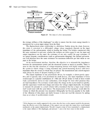
Figure 23 The chain of a flow measurement.
the average stiffness of the diaphragm* in order to ensure that the strain energy transfer is
maximized for a given input energy from the fluid.
The displacement–strain relationship is a definition. Further along the chain, however,
this strain is converted to a differential voltage whose magnitude depends on the input
impedance of the galvanometer, which is loading the bridge. For bridges constructed with
the same resistance in each arm, whether the resistors are active gages or not, the input and
output impedances are the same: the resistance of one arm, usually the gage resistance. If
we ignore dynamic considerations (such as galvanometer damping), the optimal galvanom-
eter will therefore have the same resistance for maximum deflection per unit strain as one
gage in the bridge.
At the measurement interface, therefore, the objective is to mismatch the impedances
between the measurement system and the measured system as much as possible. There is
more to this than the selections of voltage-measuring devices with higher impedance than
the system in which voltage is being measured and current-measuring devices with lower
impedance than the circuits in which they are placed. The measurement and control engineer
must always be aware of dynamic loading as well.
The output impedance of any piezoelectric device, for example, is almost purely capac-
itive and is typically only a few picofarads for small devices. The input impedance of most
oscilloscopes is a parallel combination of 1 M and 100 pF. Either or both of those would
load a piezoelectric device to near uselessness, even though for most other purposes they
are high impedances The resistance would reduce the charge on the crystal much too quickly,
and the capacitance would steal charge and reduce the voltage output drastically. An attempt
to measure the pressure in a small volume with a transducer that has a large swept volume
itself would meet with the same failure: The displacement of the transducer would alter the
volume in which the pressure was measured. Holography has become popular in the study
of the vibration of thin plates and shells because it does not load the structure by adding
mass as an array of accelerometers would.
*If the diagram were rigidly supported in the center, then the force on the support would be the pressure
times the effective area of the diaphragm. If the support were not rigid, this output force would depend
nonlinearly on the support displacement. The plot’s negative slope of force transmitted vs. displacement
is the output stiffness of the diaphragm, and pressure area is the force source in this model.