
Page 74 - Mechanical Engineers' Handbook (Volume 2)
P. 74
6 Measurement Systems 63
6.2 Dynamic Interactions in Instrument Systems
It is not only the steady-state loading of a measurement that is of concern; under many
circumstances, the unsuspected dynamics of the instrument being used will lead to erroneous
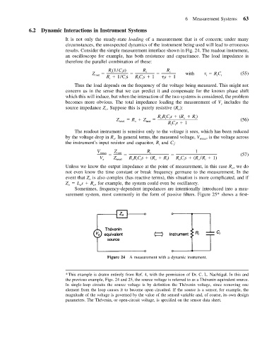
results. Consider the simple measurement interface shown in Fig. 24. The readout instrument,
an oscilloscope for example, has both resistance and capacitance. The load impedance is
therefore the parallel combination of these:
R (1/Cs) R R
i i i i with (55)
Z inst RC i
i
i
R 1/C s RCs 1 s 1
i
i
i
i
i
Thus the load depends on the frequency of the voltage being measured. This might not
concern us in the sense that we can predict it and compensate for the known phase shift
which this will induce, but when the interaction of the two systems is considered, the problem
becomes more obvious. The total impedance loading the measurement of V includes the
s
source impedance Z . Suppose this is purely resistive (R ):
o
o
RR C s (R R )
Z total R Z inst oi i o i (56)
o
RCs 1
i
i
The readout instrument is sensitive only to the voltage it sees, which has been reduced
by the voltage drop in R . In general terms, the measured voltage, V meas , is the voltage across
o
the instrument’s input resistor and capacitor, R and C :
i
i
V meas Z inst R i 1 (57)
V s Z total R R C s (R R ) RC s (R /R 1)
o
o
i
i
o
i
i
oi
Unless we know the output impedance at the point of measurement, in this case R ,we do
o
not even know the time constant or break frequency germane to the measurement. In the
event that Z is also complex (has reactive terms), this situation is more complicated, and if
o
Z L s R , for example, the system could even be oscillatory.
o
o
o
Sometimes, frequency-dependent impedances are intentionally introduced into a mea-
surement system, most commonly in the form of passive filters. Figure 25* shows a first-
Figure 24 A measurement with a dynamic instrument.
*This example is drawn entirely from Ref. 4, with the permission of Dr. C. L. Nachtigal. In this and
´
the previous example, Figs. 24 and 25, the source voltage is referred to as a Thevenin equivalent source.
´
In single-loop circuits the source voltage is by definition the Thevenin voltage, since removing one
element from the loop causes it to become open circuited. If the source is a sensor, for example, the
magnitude of the voltage is governed by the value of the sensed variable and, of course, its own design
´
parameters. The Thevenin, or open-circuit voltage, is specified on the sensor data sheet.