
Page 75 - Mechanical Engineers' Handbook (Volume 2)
P. 75
64 Input and Output Characteristics
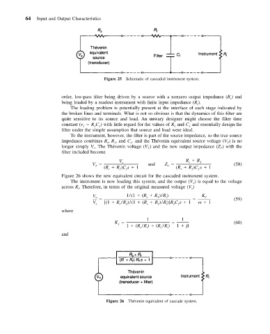
Figure 25 Schematic of cascaded instrument system.
order, low-pass filter being driven by a source with a nonzero output impedance (R ) and
s
being loaded by a readout instrument with finite input impedance (R ).
i
The loading problem is potentially present at the interface of each stage indicated by
the broken lines and terminals. What is not so obvious is that the dynamics of this filter are
quite sensitive to its source and load. An unwary designer might choose the filter time
constant ( R C ) with little regard for the values of R and C and essentially design the
ƒ
ƒ
ƒ
ƒ
ƒ
filter under the simple assumption that source and load were ideal.
To the instrument, however, the filter is part of the source impedance, so the true source
impedance combines R , R , and C . and the The´venin equivalent source voltage (V )isno
ƒ
ƒ
s
T
longer simply V . The The´venin voltage (V ) and the new output impedance (Z ) with the
T
T
s
filter included become
R R ƒ
s
V s
V and Z (58)
T
T
(R R )Cs 1 (R R )Cs 1
ƒ
ƒ
ƒ
ƒ
s
s
Figure 26 shows the new equivalent circuit for the cascaded instrument system.
The instrument is now loading this system, and the output (V ) is equal to the voltage
o
across R . Therefore, in terms of the original measured voltage (V )
s
i
1/(1 (R R )/R ) K
V o s ƒ i ƒ
(59)
ƒ
ƒ
V s [(1 R /R )/(1 (R R )/R )]RCs 1 s 1
s
ƒ
ƒ
s
i
where
1 1
K (60)
ƒ
1 (R /R ) (R /R ) 1
s
ƒ
i
i
and
Figure 26 Thevenin equivalent of cascade system.
´