
Page 69 - Mechanical Engineers' Handbook (Volume 2)
P. 69
58 Input and Output Characteristics
as an electromagnetic torque source while constant current is supplied, motor K i ,
m armature
the mechanical output impedance viewed at the motor shaft is the rotor inertia between the
output shaft and the electromagnetic torque source:
Z o motor shaft with J armature s (48)
constant armature current
During acceleration and deceleration, the optimal load impedance (Z load ) will be equal
to the motor inertia, and the available electromagnetic torque will be shared equally by the
motor armature and the load.
The load given in this example is primarily massive, so with reflection through the
screw, the load inertia is computed as the load inertia times the square of the transducer
ratio (p for the screw; see Table 2):
Z load pM load s (49)
2
To the extent possible, the pitch of the screw or the inertia of the motor should be chosen
to achieve this match. Failing both of those options, a gear box should be placed between
the screw and the motor to accomplish the match required.
5.2 Impedance Requirements for Mixed Systems
When a source characteristic is primarily real or static (so that the source impedance is
resistive) and the load is reactive or dynamic (dominated by energy storage elements), then
impedance matching in the strictest sense is impossible, and the concept of passing the load
line through the source characteristic at the maximum power point does not make sense.
How then does one match a static source to a dynamic load or the reverse?
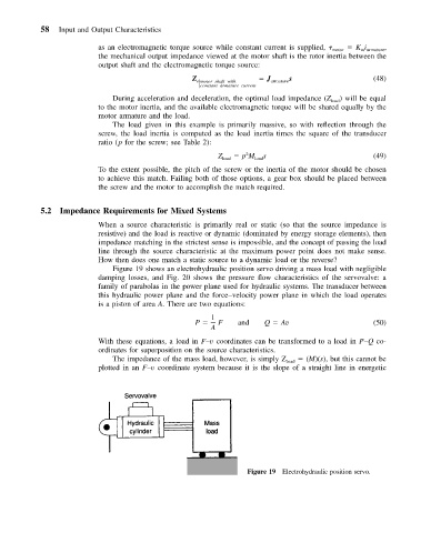
Figure 19 shows an electrohydraulic position servo driving a mass load with negligible
damping losses, and Fig. 20 shows the pressure flow characteristics of the servovalve: a
family of parabolas in the power plane used for hydraulic systems. The transducer between
this hydraulic power plane and the force–velocity power plane in which the load operates
is a piston of area A. There are two equations:
1
P F and Q Av (50)
A
With these equations, a load in F–v coordinates can be transformed to a load in P–Q co-
ordinates for superposition on the source characteristics.
The impedance of the mass load, however, is simply Z load (M)(s), but this cannot be
plotted in an F–v coordinate system because it is the slope of a straight line in energetic
Figure 19 Electrohydraulic position servo.