
Page 66 - Mechanical Engineers' Handbook (Volume 2)
P. 66
4 Operating Point of Static Systems 55
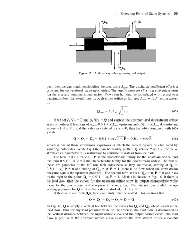
Figure 15 A three-way valve geometry and output.
pull, then we can nondimensionalize the area using A max . The discharge coefficient (C )is a
d
constant for conventional valve geometries. The supply pressure (P ) is a convenient term
S
for the pressure nondimensionalization. Flows can be nondimensionalized with respect to a
maximum flow that would pass through either orifice at full area A max with P acting across
S
it:
2
Q max CA max
P S (45)
d
If we set P /P P and Q /Q Q and express the upstream and downstream orifice
L S L S
sizes as push–pull fractions of A , 0.5(1 x)A upstream and 0.5(1 x)A downstream,
max max max
where 1 x 1 and the valve is centered for x 0, then Eq. (44) combined with (45)
yields
Q Q Q 0.5(1 x) 1 P 0.5(1 x) P (46)
u
d
which is one of those unfortunate equations in which the radical cannot be eliminated by
squaring both sides. While Eq. (46) can be readily plotted, Q versus P with x (the valve
stroke) as a parameter, it is instructive to construct it instead from its parts.
The term 0.5(1 x) 1 P is the characteristic family for the upstream orifice, and
the term 0.5(1 x) P is the characteristic family for the downstream orifice. The first of
these are parabolas to the left (on their sides because they are roots), starting at Q
u
0.5(1 x), P 0 and ending at Q 0, P 1 (there is no flow when the downstream
u
pressure equals the upstream pressure). The second term starts at Q 0, P 0 and rises
d
to the right to the points Q 0.5(1 x), P 1. All this is shown in Fig. 16. If there is
d
no load flow, then the curves for the upstream orifice show its output characteristic while
those for the downstream orifice represent the only load. The intersections predict the op-
erating pressures for Q 0 as the valve is stroked, 1 x 1.
If there is a load flow (Q), then continuity must be served. This requires that
Q Q Q → Q Q Q d (47)
u
u
d
In Fig. 16, Q is simply a vertical bar between the curves for Q and Q whose length is the
d
u
load flow. Thus for any load pressure value on the abscissa, the load flow is determined as
the vertical distance between the input orifice curve and the output orifice curve. The load
flow is positive if the upstream orifice curve is above the downstream orifice curve but