
Page 68 - Mechanical Engineers' Handbook (Volume 2)
P. 68
5 Transforming the Operating Point 57
5 TRANSFORMING THE OPERATING POINT
It is often not among the system designer’s options to choose either the output impedance
of the power source in the system or the input impedance of the load that must drive. The
only recourse at that point is to insert a transformer, transducer, or gyrator in the system if
it does not already contain one or to vary the modulus of the two-port element if it does. In
the old tube-type audio systems, the output impedance of the push–pull power tubes ex-
ceeded 1000 while the input impedance of the speakers available then was 4, 8, or 16 .
To match the amplifier to the load, each channel had a large transformer for speaker con-
nections with taps having turns ratios of 1000/4, 1000/8, and 1000/16. With this
arrangement, maximum power transfer was assured down to the lowest frequencies for which
the transformers were designed.
5.1 Transducer-Matched Impedances
Suppose a permanent direct current (dc) magnet servomotor is to drive a screw that, in turn,
drives a mass, perhaps a machine-tool table. If the objective is to minimize the move time
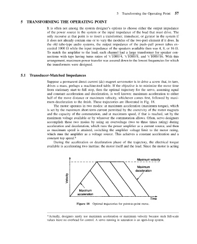
from stationary start to full stop, then the optimal trajectory for the servo, assuming equal
and constant acceleration and deceleration, is well known: maximum acceleration to either
half of the move distance or maximum velocity, whichever comes first, followed by maxi-
mum deceleration to the finish. These trajectories are illustrated in Fig. 18.
The motor operates in two modes: at maximum acceleration (maximum torque), which
is set by the maximum short-term current permitted by the coercivity of the motor magnets
and the capacity of the commutation, and at maximum speed, if that is reached, set by the
maximum voltage available or by whatever the commutation allows. Often, servo designers
accomplish these two modes by using an overvoltage (two to three times rating) during
acceleration and deceleration, which runs the power amplifier as a current source, and then
as maximum speed is attained, switching the amplifier voltage limit to the motor rating,
which runs the amplifier as a voltage source. This achieves a constant acceleration and a
constant top speed.*
During the acceleration or deceleration phase of the trajectory, the electrical torque
available is accelerating two inertias: the motor itself and the load. Since the motor is acting
Figure 18 Optimal trajectories for point-to-point move.
*Actually, designers rarely use maximum acceleration or maximum velocity because such full-scale
values leave no overhead for control. A servo running in saturation is an open-loop system.