
Page 357 - Mechanical Engineers' Handbook (Volume 4)
P. 357
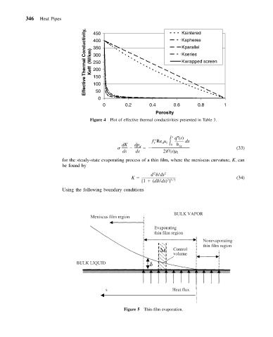
346   Heat Pipes           450                                Ksintered

                                   Effective Thermal Conductivity,   Keff  (W/km)  400  Kparallel

                                                                         Kspheres
                                      350
                                                                         Kseries
                                      300
                                                                         Kwrapped screen
                                      250
                                      200
                                      150
                                      100
                                       50
                                        0
                                          0       0.2       0.4       0.6      0.8       1
                                                              Porosity
                                     Figure 4 Plot of effective thermal conductivities presented in Table 3.


                                                             ƒ Re     s  q (s)

                                                 dK   dp d    I  s  l  0 h ƒg  ds
                                                                                              (33)
                                                                   3
                                                 ds    ds        2  (s)  l
                          for the steady-state evaporating process of a thin film, where the meniscus curvature, K, can
                          be found by

                                                              2
                                                             d  /ds 2
                                                     K                                        (34)
                                                                   23 / 2
                                                         [1   (d /ds)]
                          Using the following boundary conditions


                                                                      BULK VAPOR
                                     Meniscus film region

                                                              Evaporating
                                                              thin film region
                                                                                 Nonevaporating
                                                                                 thin film region
                                                                 s   Control
                                                                     volume
                               BULK LIQUID                  δ


                                           s
                                           s                         Heat flux


                                                  Figure 5 Thin-film evaporation.