Page 361 - Mechanical Engineers' Handbook (Volume 4)
P. 361

350   Heat Pipes


                                              Groove No. 1            Groove No. 2

                                          45      Groove No. 1
                                         Temperature Drop (C)  30
                                          40
                                                  Groove No. 2
                                          35
                                          25
                                          20
                                          15
                                          10
                                           5
                                           0
                                             0    10    20    30    40    50    60
                                                         Input Power (W)
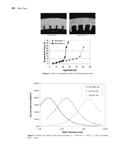
                                       Figure 8 Groove configuration effect on the temperature drops.


                               1200.00
                                                                                rb=0.635 mm
                               1000.00
                                                                                rb=0.10 mm
                             Dry-out Heat Flux (kW/m 2 )  600.00
                                                                                rb=0.01 mm
                               800.00


                               400.00


                               200.00


                                 0.00
                                   0.01                0.10               1.00               10.00
                                                         Wick Thickness (mm)
                          Figure 9 Particle size effect on the dryout heat flux (L   0.254 m; 	   43%; L H   0.01 m; working
                          fluid   water).
   356   357   358   359   360   361   362   363   364   365   366