
Page 390 - Mechanical Engineers' Handbook (Volume 4)
P. 390
1 Thermal Modeling 379
reducing the largest resistances along a specified thermal path and/or providing parallel paths
for heat removal from a critical area.
While the thermal resistances associated with various paths and thermal transport mech-
anisms constitute the ‘‘building blocks’’ in performing a detailed thermal analysis, they have
also found widespread application as ‘‘figures-of-merit’’ in evaluating and comparing the
thermal efficacy of various packaging techniques and thermal management strategies.
Definition
The thermal performance of alternative chip and packaging techniques is commonly com-
pared on the basis of the overall (junction-to-coolant) thermal resistance, R . This packaging
T
figure-of-merit is generally defined in a purely empirical fashion,
T T
R j fl (K/W) (24)
T
q c
where T and T are the junction and coolant (fluid) temperatures, respectively, and q is the
j
c
fl
chip heat dissipation.
Unfortunately, however, most measurement techniques are incapable of detecting the
actual junction temperature, that is, the temperature of the small volume at the interface of
p-type and n-type semiconductors. Hence, this term generally refers to the average temper-
ature or a representative temperature on the chip. To lower chip temperature at a specified
power dissipation, it is clearly necessary to select and/or design a chip package with the
lowest thermal resistance.
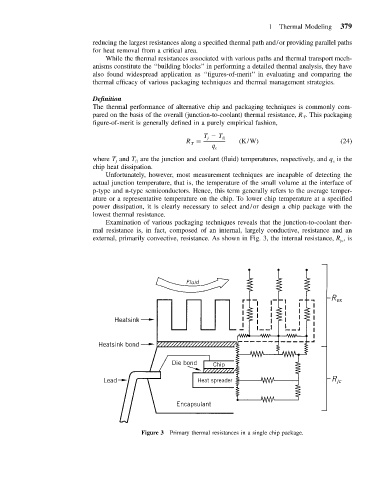
Examination of various packaging techniques reveals that the junction-to-coolant ther-
mal resistance is, in fact, composed of an internal, largely conductive, resistance and an
external, primarily convective, resistance. As shown in Fig. 3, the internal resistance, R ,is
jc
Figure 3 Primary thermal resistances in a single chip package.