Page 393 - Mechanical Engineers' Handbook (Volume 4)
P. 393
382   Cooling Electronic Equipment
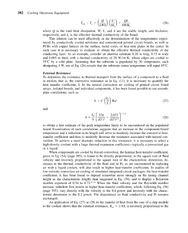
                                                    T                   QL
                                                           Q
                                                                 L
                                                                  2
                                               T ctr  o                                       (26)
                                                          LW     8k e  8W k e
                          where Q is the total heat dissipation, W, L, and   are the width, length, and thickness,
                          respectively, and k is the effective thermal conductivity of the board.
                                        e
                             This relation can be used effectively in the determination of the temperatures experi-
                          enced by conductively cooled substrates and conventional printed circuit boards, as well as
                          PCBs with copper lattices on the surface, metal cores, or heat-sink plates in the center. In
                          each case it is necessary to evaluate or obtain the effective thermal conductivity of the
                          conducting layer. As an example, consider an alumina substrate 0.20 m long, 0.15 m wide
                          and 0.005 m thick with a thermal conductivity of 20 W/m K, whose edges are cooled to
                          35 C by a cold plate. Assuming that the substrate is populated by 30 components, each
                          dissipating 1 W, use of Eq. (26) reveals that the substrate center temperature will equal 85 C.

                          External Resistance
                          To determine the resistance to thermal transport from the surface of a component to a fluid
                          in motion, that is, the convective resistance as in Eq. (11), it is necessary to quantify the
                          heat transfer coefficient, h. In the natural convection air cooling of printed circuit board
                          arrays, isolated boards, and individual components, it has been found possible to use smooth-
                          plate correlations, such as
                                                       h   C        n
                                                              k
                                                               fl
                                                              L  Ra                           (27)
                          and
                                                  h       576   2.073    1/2
                                                      k
                                                      fl
                                                           12
                                                                  10.5
                                                      b  (El )     (El )                      (28)
                          to obtain a first estimate of the peak temperature likely to be encountered on the populated
                          board. Examination of such correlations suggests that an increase in the component/board
                          temperature and a reduction in its length will serve to modestly increase the convective heat-
                          transfer coefficient and thus to modestly decrease the resistance associated with natural con-
                          vection. To achieve a more dramatic reduction in this resistance, it is necessary to select a
                          high-density coolant with a large thermal expansion coefficient—typically a pressurized gas
                          or a liquid.
                             When components are cooled by forced convection, the laminar heat-transfer coefficient,
                          given in Eq. (54) (page 395), is found to be directly proportional, to the square root of fluid
                          velocity and inversely proportional to the square root of the characteristic dimension. In-
                          creases in the thermal conductivity of the fluid and in Pr, as are encountered in replacing
                          air with a liquid coolant, will also result in higher heat-transfer coefficients. In studies of
                          low-velocity convective air cooling of simulated integrated circuit packages, the heat-transfer
                          coefficient, h, has been found to depend somewhat more strongly on Re (using channel
                          height as the characteristic length) than suggested in Eq. (54), and to display a Reynolds
                          number exponent of 0.54 to 0.72. 8–10  When the fluid velocity and the Reynolds number
                          increase, turbulent flow results in higher heat-transfer coefficients, which, following Eq. (56)
                          (page 395), vary directly with the velocity to the 0.8 power and inversely with the charac-
                          teristic dimension to the 0.2 power. The dependence on fluid conductivity and Pr remains
                          unchanged.
                             An application of Eq. (27) or (28) to the transfer of heat from the case of a chip module
                          to the coolant shows that the external resistance, R   1/hS, is inversely proportional to the
                                                                 ex

