
Page 392 - Mechanical Engineers' Handbook (Volume 4)
P. 392
1 Thermal Modeling 381
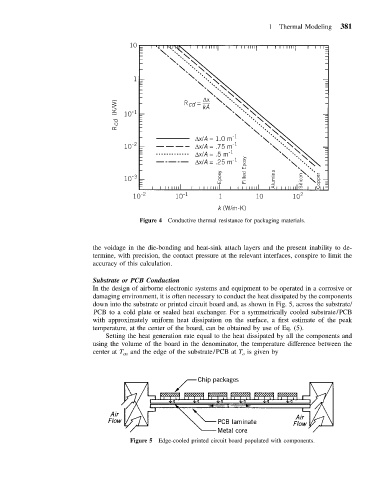
Figure 4 Conductive thermal resistance for packaging materials.
the voidage in the die-bonding and heat-sink attach layers and the present inability to de-
termine, with precision, the contact pressure at the relevant interfaces, conspire to limit the
accuracy of this calculation.
Substrate or PCB Conduction
In the design of airborne electronic systems and equipment to be operated in a corrosive or
damaging environment, it is often necessary to conduct the heat dissipated by the components
down into the substrate or printed circuit board and, as shown in Fig. 5, across the substrate/
PCB to a cold plate or sealed heat exchanger. For a symmetrically cooled substrate/PCB
with approximately uniform heat dissipation on the surface, a first estimate of the peak
temperature, at the center of the board, can be obtained by use of Eq. (5).
Setting the heat generation rate equal to the heat dissipated by all the components and
using the volume of the board in the denominator, the temperature difference between the
center at T ctr and the edge of the substrate/PCB at T is given by
o
Figure 5 Edge-cooled printed circuit board populated with components.