
Page 394 - Mechanical Engineers' Handbook (Volume 4)
P. 394
1 Thermal Modeling 383
wetted surface area and to the coolant velocity to the 0.5 to 0.8 power and directly propor-
tional to the length scale in the flow direction to the 0.5 to 0.2 power. It may thus be observed
that the external resistance can be strongly influenced by the fluid velocity and package
dimensions and that these factors must be addressed in any meaningful evaluation of the
external thermal resistances offered by various packaging technologies.
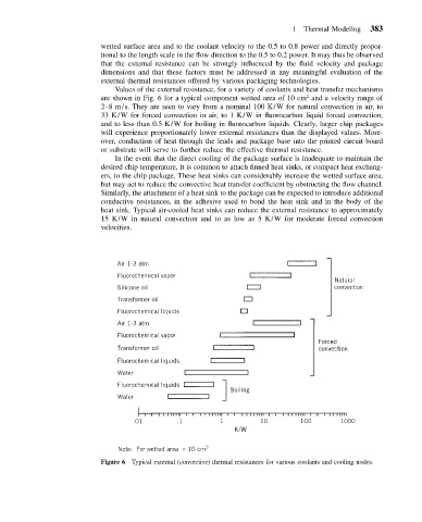
Values of the external resistance, for a variety of coolants and heat transfer mechanisms
2
are shown in Fig. 6 for a typical component wetted area of 10 cm and a velocity range of
2–8 m/s. They are seen to vary from a nominal 100 K/W for natural convection in air, to
33 K/W for forced convection in air, to 1 K/W in fluorocarbon liquid forced convection,
and to less than 0.5 K/W for boiling in fluorocarbon liquids. Clearly, larger chip packages
will experience proportionately lower external resistances than the displayed values. More-
over, conduction of heat through the leads and package base into the printed circuit board
or substrate will serve to further reduce the effective thermal resistance.
In the event that the direct cooling of the package surface is inadequate to maintain the
desired chip temperature, it is common to attach finned heat sinks, or compact heat exchang-
ers, to the chip package. These heat sinks can considerably increase the wetted surface area,
but may act to reduce the convective heat transfer coefficient by obstructing the flow channel.
Similarly, the attachment of a heat sink to the package can be expected to introduce additional
conductive resistances, in the adhesive used to bond the heat sink and in the body of the
heat sink. Typical air-cooled heat sinks can reduce the external resistance to approximately
15 K/W in natural convection and to as low as 5 K/W for moderate forced convection
velocities.
Figure 6 Typical external (convective) thermal resistances for various coolants and cooling nodes.