
Page 399 - Mechanical Engineers' Handbook (Volume 4)
P. 399
388 Cooling Electronic Equipment
In the case of isoflux parallel-plate arrays, the power dissipation may be maximized by
increasing the number of plates indefinitely. Thus, it is more practical to define the optimum
channel spacing for an array of isoflux plates as the spacing, which will yield the maximum
volumetric heat dissipation rate per unit temperature difference. Despite this distinction, the
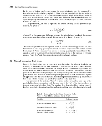
optimum spacing is found in the same manner. The optimal spacing for different conditions
is listed in Table 3. 42
The parameter b opt in Table 3 represents the optimal spacing, and the plate to air pa-
rameter P is given as
2
C ( ) g
T 0
p
ƒ
P (38)
kL
ƒƒ
where
T is the temperature difference between the printed circuit board and the ambient
0
temperature at the inlet of the channel. The parameter R in Table 3 is given by
2
C ( ) g q
p
ƒ
R (39)
2
kL
ƒ
These smooth-plate relations have proven useful in a wide variety of applications and have
been shown to yield very good agreement with measured empirical results for heat transfer
from arrays of PCBs. However, when applied to closely spaced printed circuit boards these
equations tend to underpredict heat transfer in the channel due to the presence of between-
package ‘‘wall flow’’ and the nonsmooth nature of the channel surfaces.
2.2 Natural Convection Heat Sinks
Despite the decades-long rise in component heat dissipation, the inherent simplicity and
reliability of buoyantly driven flow continues to make the use of natural convection heat
sinks, the cooling technology of choice for a large number of electronic applications. An
understanding of natural convection heat transfer from isothermal, parallel-plate channels
provides the theoretical underpinning for the conceptual design of natural convection cooled
plate–fin heat sinks. However, detailed design and optimization of such fin structures requires
an appreciation for the distinct characteristics of such phenomena as buoyancy-induced fluid
flow in the interfin channels and conductive heat flow in the plate fins.
The presence of the heat-sink ‘‘base,’’ or prime surface area, along one edge of the
parallel-plate channel, contrasting with the open edge at the ‘‘tip’’ of the fins, introduces an
inherent asymmetry in the flow field. The resulting three-dimensional flow pattern generally
involves some inflow from (and possibly outflow through) the open edge. For relatively small
Table 3 Optimum Spacing for Natural Convection Cooled
Arrays of Vertical Plates or Printed Circuit Boards
Condition Optimum Spacing
2.714
Symmetric isothermal plates b opt
P 1/4
2.154
Asymmetric isothermal plates b opt
P 1/4
Symmetric isoflux plates b opt 1.472R 0.2
Asymmetric isoflux plates b opt 1.169R 0.2