
Page 402 - Mechanical Engineers' Handbook (Volume 4)
P. 402
2 Heat-Transfer Correlations for Electronic Equipment Cooling 391
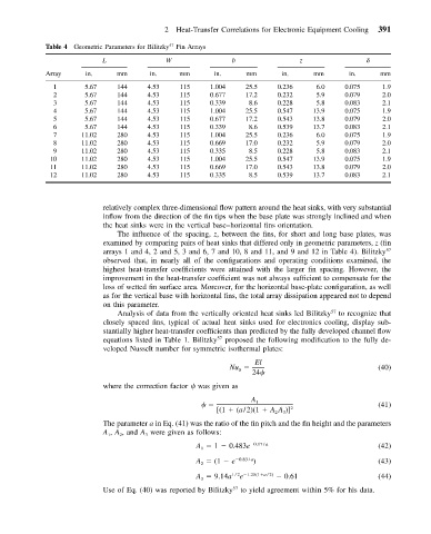
Table 4 Geometric Parameters for Bilitzky Fin Arrays
57
L W b z
Array in. mm in. mm in. mm in. mm in. mm
1 5.67 144 4.53 115 1.004 25.5 0.236 6.0 0.075 1.9
2 5.67 144 4.53 115 0.677 17.2 0.232 5.9 0.079 2.0
3 5.67 144 4.53 115 0.339 8.6 0.228 5.8 0.083 2.1
4 5.67 144 4.53 115 1.004 25.5 0.547 13.9 0.075 1.9
5 5.67 144 4.53 115 0.677 17.2 0.543 13.8 0.079 2.0
6 5.67 144 4.53 115 0.339 8.6 0.539 13.7 0.083 2.1
7 11.02 280 4.53 115 1.004 25.5 0.236 6.0 0.075 1.9
8 11.02 280 4.53 115 0.669 17.0 0.232 5.9 0.079 2.0
9 11.02 280 4.53 115 0.335 8.5 0.228 5.8 0.083 2.1
10 11.02 280 4.53 115 1.004 25.5 0.547 13.9 0.075 1.9
11 11.02 280 4.53 115 0.669 17.0 0.543 13.8 0.079 2.0
12 11.02 280 4.53 115 0.335 8.5 0.539 13.7 0.083 2.1
relatively complex three-dimensional flow pattern around the heat sinks, with very substantial
inflow from the direction of the fin tips when the base plate was strongly inclined and when
the heat sinks were in the vertical base–horizontal fins orientation.
The influence of the spacing, z, between the fins, for short and long base plates, was
examined by comparing pairs of heat sinks that differed only in geometric parameters, z (fin
arrays 1 and 4, 2 and 5, 3 and 6, 7 and 10, 8 and 11, and 9 and 12 in Table 4). Bilitzky 57
observed that, in nearly all of the configurations and operating conditions examined, the
highest heat-transfer coefficients were attained with the larger fin spacing. However, the
improvement in the heat-transfer coefficient was not always sufficient to compensate for the
loss of wetted fin surface area. Moreover, for the horizontal base-plate configuration, as well
as for the vertical base with horizontal fins, the total array dissipation appeared not to depend
on this parameter.
Analysis of data from the vertically oriented heat sinks led Bilitzky to recognize that
57
closely spaced fins, typical of actual heat sinks used for electronics cooling, display sub-
stantially higher heat-transfer coefficients than predicted by the fully developed channel flow
equations listed in Table 1. Bilitzky 57 proposed the following modification to the fully de-
veloped Nusselt number for symmetric isothermal plates:
El
Nu (40)
0
24
where the correction factor was given as
A
1 (41)
[(1 (a/2)(1 AA )] 2
2
3
The parameter a in Eq. (41) was the ratio of the fin pitch and the fin height and the parameters
A , A , and A were given as follows:
1
3
2
A 1 0.483e 0.17 / a (42)
1
A (1 e 0.83 / a ) (43)
2
e
A 9.14a 1/2 1.25(1 a /2) 0.61 (44)
3
Use of Eq. (40) was reported by Bilitzky to yield agreement within 5% for his data.
57