
Page 401 - Mechanical Engineers' Handbook (Volume 4)
P. 401
390 Cooling Electronic Equipment
air with the cooler ambient fluid. In this study it was observed, for the first time, that for
any given interfin spacing there is an optimum fin height, b, beyond which thermal perform-
ance, per unit surface area, deteriorates.
In 1986 Bilitzky 57 completed a comprehensive investigation of natural convection heat
transfer from multiple heat-sink geometries that differed, primarily, in fin height and spacing.
The heat sinks were operated at different heat dissipations as well as different angles of
inclination and orientation. Twelve distinct heat sinks and a flat plate were tested in a room
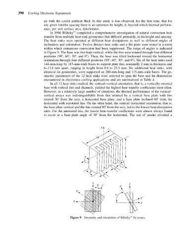
within which extraneous convection had been suppressed. The range of angles is indicated
in Figure 9. The base was first kept vertical, while the fins were rotated through four different
positions (90 ,60 ,30 , and 0 ). Then, the base was tilted backward toward the horizontal
orientation through four different positions (90 ,60 ,30 , and 0 ). Six of the heat sinks used
144-mm-long by 115-mm-wide bases to support plate fins, nominally 2 mm in thickness and
6–13.8 mm apart, ranging in height from 8.6 to 25.5 mm. Six additional heat sinks, with
identical fin geometries, were supported on 280-mm-long and 115-mm-wide bases. The ge-
ometric parameters of the 12 heat sinks were selected to span the base and fin dimensions
encountered in electronics cooling applications and are summarized in Table 4.
In all 12 heat sinks studied, the vertical–vertical orientation, that is, a vertically oriented
base with vertical fins and channels, yielded the highest heat-transfer coefficients most often.
However, in a relatively large number of situations, the thermal performance of the vertical–
vertical arrays was indistinguishable from that attained by a vertical base plate with fins
rotated 30 from the axis, a horizontal base plate, and a base plate inclined 60 from the
horizontal with unrotated fins. On the other hand, the vertical–horizontal orientation, that is,
the base plate vertical and the fins rotated 90 from the axis, led to the lowest heat-dissipation
rates. For the unrotated fins, the lowest heat-transfer coefficients were almost always found
to occur at a base-plate angle of 30 from the horizontal. The use of smoke revealed a
z
W
L
x
y
b
z
z z
z
z
x
y
x
y
Figure 9 Geometry and orientation of Bilitzky fin arrays.
57