
Page 400 - Mechanical Engineers' Handbook (Volume 4)
P. 400
2 Heat-Transfer Correlations for Electronic Equipment Cooling 389
fin spacings with long and low fins, this edge flow may result in a significant decrease in
the air temperature between the fins and dramatically alter the performance of such heat
sinks. For larger fin spacings, and especially with wide, thick fins, the edge flow may well
be negligible.
Heat flow in extended surfaces must result in a temperature gradient at the fin base.
When heat flow is from the base to the ambient, the temperature decreases along the fin,
and the average fin surface excess temperature (i.e., T fin T ) is typically between 50 and
air
90% of the base excess temperature. As a consequence of the temperature distribution on
the fin surface, exact analytic determination of the heat-sink capability requires a combined
(or conjugate) solution of the fluid flow in the channel and heat flow in the fin. Due to the
complexity of such a conjugate analysis, especially in the presence of three-dimensional flow
effects, the thermal performance of heat sinks is frequently based on empirical results. In
recent years, extensive use has also been made of detailed numerical solutions to quantify
heat-sink performance. Alternatively, a satisfactory estimate of heat-sink capability can gen-
erally be obtained by decoupling the flow and temperature fields and using an average heat-
transfer coefficient, along with an average fin surface temperature, to calculate the thermal
transport from the fins to the ambient air.
55
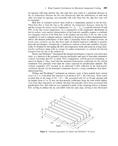
Starner and McManus investigated the thermal performance of natural convection heat
sinks, as a function of the geometry (spacing and height) and angle of base-plate orientation
(vertical, horizontal and 45 ), in detail. Their configuration, with the present terminology, is
shown in Figure 8. They found that the measured heat-transfer coefficients for the vertical
orientation were generally lower than the values expected for parallel-plate channels. The
inclined orientation (45 ) resulted in an additional 5–20% reduction in the heat-transfer
coefficient. Results for the horizontal orientation showed a strong contribution from three-
dimensional flow.
Welling and Wooldridge 56 performed an extensive study of heat transfer from vertical
arrays of 2- to 3-mm-thick fins attached to an identical 203 66.3-mm base. Their results
revealed that, in the range of 0.6 El 100, associated with 4.8- to 19-mm spacings and
fin heights from 6.3 to 19 mm, the heat-transfer coefficients along the total wetted surface
were lower than attained by an isolated, flat plate but generally above those associated with
parallel-plate flow. This behavior was explained in terms of the competing effects of channel
flow, serving to preheat the air, and inflow from the open edge, serving to mix the heated
z
L
b
Fin W
Base
55
Figure 8 Geometric parameters for Starner and McManus fin arrays.