
Page 410 - Mechanical Engineers' Handbook (Volume 4)
P. 410
2 Heat-Transfer Correlations for Electronic Equipment Cooling 399
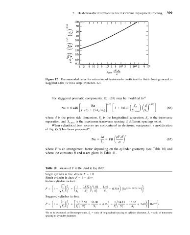
Figure 12 Recommended curve for estimation of heat-transfer coefficient for fluids flowing normal to
staggered tubes 10 rows deep (from Ref. 22).
For staggered prismatic components, Eq. (65) may be modified to 29
Nu 0.446 Re 1 0.639
0.57
0.172
d
S
T
(1/6) (5A /A ) S T,max S L (66)
n
0
where d is the prism side dimension, S is the longitudinal separation, S is the transverse
L
T
separation, and S T,max is the maximum transverse spacing if different spacings exist.
When cylindrical heat sources are encountered in electronic equipment, a modification
of Eq. (57) has been proposed :
30
Vd
hd FB n
Nu (67)
k ƒ
where F is an arrangement factor depending on the cylinder geometry (see Table 10) and
where the constants B and n are given in Table 11.
Table 10 Values of F to Be Used in Eq. (67) a
Single cylinder in free stream: F 1.0
Single cylinder in duct: F 1 d/w
In-line cylinders in duct:
F 1 1 1 1 1.81 1.46 0.318 [Re 0.526 (0.354 / S ) ]
0.872
S L S L S T S T
S T 2 2 T
Staggered cylinders in duct:
F 1 1 1 16.80 4.15 15.33 3.69
1 15.50
1 14.15
0.13
S L S T S T S L S T S T
S T 2 2 Re
a
Re to be evaluated at film temperature. S L ratio of longitudinal spacing to cylinder diameter. S T ratio of transverse
spacing to cylinder diameter.