
Page 408 - Mechanical Engineers' Handbook (Volume 4)
P. 408
2 Heat-Transfer Correlations for Electronic Equipment Cooling 397
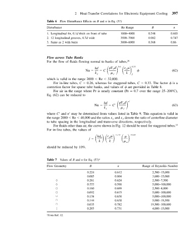
Table 6 Flow Disturbance Effects on B and n in Eq. (57)
Disturbance Re Range B n
1. Longitudinal fin, 0.1d thick on front of tube 1000–4000 0.248 0.603
2. 12 longitudinal grooves, 0.7d wide 3500–7000 0.082 0.747
3. Same as 2 with burrs 3000–6000 0.368 0.86
Flow across Tube Banks
For the flow of fluids flowing normal to banks of tubes, 26
0.6
Vd
c
hd C 0.33
p
Nu (62)
k k
ƒ ƒ ƒ
which is valid in the range 2000 Re 32,000.
For in-line tubes, C 0.26, whereas for staggered tubes, C 0.33. The factor is a
correction factor for sparse tube banks, and values of are provided in Table 8.
For air in the range where Pr is nearly constant (Pr 0.7 over the range 25–200 C),
Eq. (62) can be reduced to
Vd
hd C
n
Nu (63)
k ƒ ƒ
where C
and n
may be determined from values listed in Table 9. This equation is valid in
the range 2000 Re 40,000 and the ratios x and x denote the ratio of centerline diameter
L T
to tube spacing in the longitudinal and transverse directions, respectively.
For fluids other than air, the curve shown in Fig. 12 should be used for staggered tubes. 22
For in-line tubes, the values of
j 0.14
c
1/3
p
hd 0
k k w
should be reduced by 10%.
Table 7 Values of B and n for Eq. (57) a
Flow Geometry B n Range of Reynolds Number
0.224 0.612 2,500–15,000
0.085 0.804 3,000–15,000
0.261 0.624 2,500–7,500
0.222 0.588 5,000–100,000
▫ 0.160 0.699 2,500–8,000
▫ 0.092 0.675 5,000–100,000
0.138 0.638 5,000–100,000
0.144 0.638 5,000–19,500
0.035 0.782 19,500–100,000
0.205 0.731 4,000–15,000
a From Ref. 12.