
Page 163 - Mechanics of Asphalt Microstructure and Micromechanics
P. 163
Mixture T heor y and Micromechanics Applications 155
P
P 3
P 1 P 2
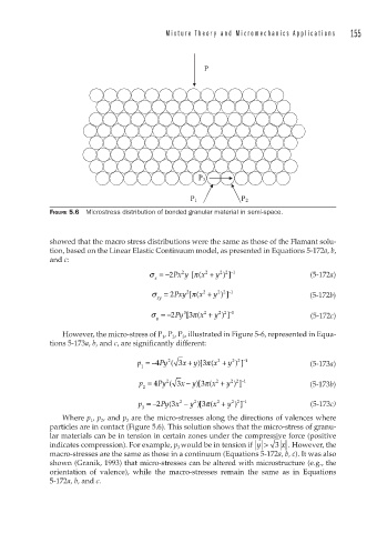
FIGURE 5.6 Microstress distribution of bonded granular material in semi-space.
showed that the macro stress distributions were the same as those of the Flamant solu-
tion, based on the Linear Elastic Continuum model, as presented in Equations 5-172a, b,
and c:
π x +
2
2 2
σ =−2 Px y [( 2 y ) ] −1 (5-172a)
x
σ = 2 Pxy [( 2 y ) ] −1 (5-172b)
π x +
2
2 2
xy
2 2
2
3
[
σ =−2 Py 3 π x + y ) ] −1 (5-172c)
(
y
However, the micro-stress of P 1 , P 2 , P 3 , illustrated in Figure 5-6, represented in Equa-
tions 5-173a, b, and c, are significantly different:
2 2 −
π
+
2
2
)
[
p =− 4 Py ( 3 x y 3 ( x + y ) ] 1 (5-173a)
1
π
−
2 2 −
2
2
[
p = 4 Py ( 3 x y 3 ( x + y ) ] 1 (5-173b)
)
2
2 2 −
p =− 2 Py x −( 3 2 y )[ 3 ( x + y ) ] 1 (5-173c)
π
2
2
3
Where p 1 , p 2 , and p 3 are the micro-stresses along the directions of valences where
particles are in contact (Figure 5.6). This solution shows that the micro-stress of granu-
lar materials can be in tension in certain zones under the compressive force (positive
indicates compression). For example, p 3 would be in tension if y > 3 x . However, the
macro-stresses are the same as those in a continuum (Equations 5-172a, b, c). It was also
shown (Granik, 1993) that micro-stresses can be altered with microstructure (e.g., the
orientation of valence), while the macro-stresses remain the same as in Equations
5-172a, b, and c.