Page 166 - Mechanics of Asphalt Microstructure and Micromechanics
P. 166

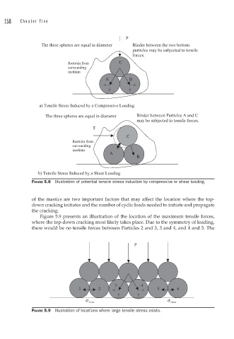
158   Ch a p t e r  Fiv e


                                                   P
                 The three spheres are equal in diameter   Binder between the two bottom
                                                      particles may be subjected to tensile
                                                      forces.
                            Restrain from       C
                            surrounding
                            medium
                                           A        B


                 a) Tensile Stress Induced by a Compressive Loading
                   The three spheres are equal in diameter   Binder between Particles A and C
                                                       may be subjected to tensile forces.
                                      T

                                                   C
                              Restrain from
                              surrounding
                              medium
                                             A
                                                       B


                b) Tensile Stress Induced by a Shear Loading
              FIGURE 5.8  Illustration of potential tensile stress induction by compressive or shear loading.


              of the mastics are two important factors that may affect the location where the top-
              down cracking initiates and the number of cyclic loads needed to initiate and propagate
              the cracking.
                 Figure 5.9 presents an illustration of the location of the maximum tensile forces,
              where the top-down cracking most likely takes place. Due to the symmetry of loading,
              there would be no tensile forces between Particles 2 and 3, 3 and 4, and 4 and 5. The


                                                      P


                                               3         4
                                1       2                      5       6

                                   σ                               σ
                                    t max                            t  max
              FIGURE 5.9  Illustration of locations where large tensile stress exists.
   161   162   163   164   165   166   167   168   169   170   171