
Page 295 - Mechanics of Asphalt Microstructure and Micromechanics
P. 295
Applications of Discrete Element Method 287
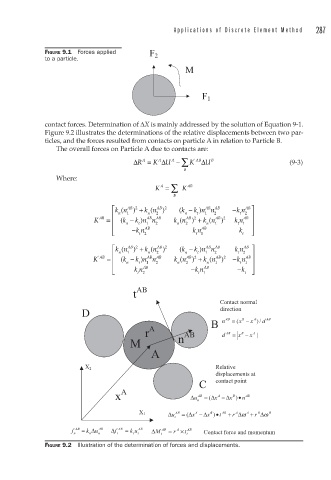
FIGURE 9.1 Forces applied F 2
to a particle.
M
F 1
contact forces. Determination of ΔX is mainly addressed by the solution of Equation 9-1.
Figure 9.2 illustrates the determinations of the relative displacements between two par-
ticles, and the forces resulted from contacts on particle A in relation to Particle B.
The overall forces on Particle A due to contacts are:
ΔR = K A ΔU − ∑ K ' AB ΔU B (9-3)
A
A
B
Where:
K = ∑ K AB
A
B
⎡ kn ) + kn ) ( k − k n n AB − k n ⎤
AB 2
AB
AB 2
A AB
(
(
)
2
⎢ n 1 n 2 n t 1 2 t AB ⎥
AB
AB 2
AB 2
)
K AB = ⎢ k ( n − k n n 2 AB kn ) + kn ) k n
(
(
t 1 ⎥
t
1
1
n
n
2
⎢ AB AB ⎥
⎣ − −kn 2 kn k t ⎦
t 1
t
⎡ kn ( 1 AB 2 kn ( AB 2 k ( n − k n n AB k n 2 A AB ⎤
) +
AB
)
)
n
t
t
1
n
2
2
B
AB 2
AB
AB 2
K ' AB = ⎢ ⎢ k ( n − k n n AB kn ) + kn ) − k n AB ⎥
(
)
(
t 1 ⎥
n
t
1
2
1
n
2
⎢ AB − AB − ⎥
⎣ kn 2 kn k t ⎦
t
t 1
t AB
Contact normal
direction
D
B n AB = x ( B − x A d / ) AB
r A AB d AB = x − x A |
B
M n
A
Relative
X 2
displacements at
C contact point
x A Δ u AB = Δ ( x − Δ x ) • n AB
B
A
n
A
A
B
A
X 1 Δ u AB = Δ ( x − Δ x B t • ) AB + r Δ ω + r Δ ω B
t
f n AB = k Δ u AB f Δ t AB = k t u t AB Δ M t AB = r A t × t AB Contact force and momentum
n
n
FIGURE 9.2 Illustration of the determination of forces and displacements.