
Page 299 - Mechanics of Asphalt Microstructure and Micromechanics
P. 299
Applications of Discrete Element Method 291
Model Key Factors Controlling Variables in PFC3D
Contact-stiffness model Normal stiffness md_kn
(Linear) Shear stiffness md_ks
Slip model Friction factor md_fric
Bonding model (parallel) Normal stiffness pb_kn
Shear stiffness pb_ks
Normal strength pb_sn
Shear strength pb_ss
Radius pb_radmult
TABLE 9.2 Key micro-variables in different contact constitutive models in PFC3D.
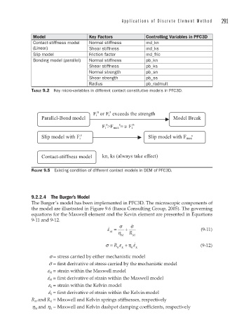
s
n
F i or F i exceeds the strength
Parallel-Bond model Model Break
s
s
F i >F max = F i n
s s
Slip model with F i Slip model with F max
Contact-stiffness model kn, ks (always take effect)
FIGURE 9.5 Existing condition of different contact models in DEM of PFC3D.
9.2.2.4 The Burger’s Model
The Burger’s model has been implemented in PFC3D. The microscopic components of
the model are illustrated in Figure 9.6 (Itasca Consulting Group, 2005). The governing
equations for the Maxwell element and the Kevin element are presented in Equations
9-11 and 9-12. ·
·
ε = σ + σ (9-11)
M η R
M M
σ = R ε + η ε · (9-12)
KK KK
s = stress carried by either mechanistic model
·
s = first derivative of stress carried by the mechanistic model
e M = strain within the Maxwell model
·
e M = first derivative of strain within the Maxwell model
e K = strain within the Kelvin model
·
e K = first derivative of strain within the Kelvin model
R M and R K = Maxwell and Kelvin springs stiffnesses, respectively
h M and h K = Maxwell and Kelvin dashpot damping coefficients, respectively