Page 298 - Mechanics of Asphalt Microstructure and Micromechanics
P. 298

290   Ch a p t e r  N i n e


              bond is that it can act in parallel with a slip model. Below are the equations governing
              the normal and shear components for both the force and moment:
                                                  n
                                             Fi =  Fi +  s                        (9-7)
                                                     Fi
                                                  n
                                            M i =  M i +  s                       (9-8)
                                                     M i
                 The elastic properties and the limit of the bond can be set up by designating the fol-
                                         n              s
              lowing factors: normal stiffness k ; shear stiffness k ; normal strength σ c; shear strength
              τc; and bond disk radius R. The equations for defining the above variables are listed in
              Table 9.1 (Itasca Consulting Group, 2005).
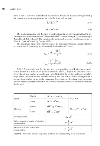
                 The maximum tensile and shear stresses of the bond periphery are calculated below
              to compare with the strengths; if exceeded, the bond would break.
                                                       s
                                                  n
                                               −F    M i
                                          σ   =    +    R                         (9-9)
                                           max  A     I
                                                 s     n
                                                Fi   M
                                          τ   =    +    R                        (9-10)
                                           max  A     I

                 Table 9.2 summarizes the key factors and corresponding variables for some consti-
              tutive models that are used in granular materials and AC. Figure 9.5 describes condi-
              tions when those models are no longer valid. Note that the contact-stiffness model al-
              ways exists (may not be the bi-linear model); the slip model would change from a
              normal-force-related status to the maximum force status as the shear force increases;
              and the parallel bond model would break when either the normal or shear force reaches
              its strength.


                                               n
                                                     n
                                                         n
                             Normal          ΔF i =− k A ΔU n
                                                         )
                                                  (
                                                           i
              Force                                               ΔU =  V  Δt
                                                                    i  i
                                                    s
                                               s
                             Shear           ΔF i =− k A ΔU  s
                                                        i
                                                     s
                                                n
                             Normal          ΔMi =− k J Δθ n  n )
                                                  (
                                                           i
              Moment                                              Δθ = ( w  B []  −  w  A [ ] ) Δt
                                                                    i   i    i
                                                s
                             Shear           ΔM i =− k  n  Δ I θ  s
                                                        i
              Bond disk area                                  A = π R 2
              Polar moment of inertia of the disk            J =  1 π R 4
              cross-section                                     2
              Moment of inertia of the disk                  I =  1  π R  4
              cross-section                                     4
              TABLE 9.1  Force and moment for parallel bond and the corresponding micro parameters.
   293   294   295   296   297   298   299   300   301   302   303