
Page 377 - Mechanics of Asphalt Microstructure and Micromechanics
P. 377
Simulation of Asphalt Compaction 369
If the compaction process is viewed as a process where air-voids are reduced and
particles are re-oriented, the mathematical representation of the air-void reduction pro-
cess (Equation 11-1) can be conveniently derived from Figure 11.2.
A = A + K • LogN (11-1)
l
v v0
where A v0 = air-void content after the first gyration;
th
A v = air-void content after the N gyration;
l
K = slope of lab compaction, or the rate of air-void content reduction.
(A v − A v0 ) corresponds to the accumulative volumetric strain. In a 1D case it is also the
vertical strain.
In other words, if density is the only parameter of interest (density may not be the
only parameter for performance), Equation 11-1 is a mathematical model. It is necessary
to associate the model parameters A v0 and K with other material properties such as ag-
l
gregate characteristics, gradation, binder content, and binder properties (temperature
dependent). However, it should be noted that the current gyratory compaction proce-
dure uses a constant pressure. How compaction varies with the magnitude of the pres-
sure may need further exploration in order to associate lab compaction to field com-
paction because field compaction has a varying pressure to different volume elements
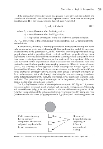
(the AC in a layer feels a varying pressure when the compactor moves). Figure 11.3 il-
lustrates this difference, where the three volume elements may be subjected to different
levels of stress or compactive efforts. If compaction curves at different compactive ef-
forts can be acquired in the lab, through calculating the compactive energy transferred
to the different elements in the field, the compaction levels at different locations can be
evaluated. This presents a logical reasoning to tackle the problem, although the math-
ematic models may take different formats.
The A v ~ LogN consolidation relationship is not unique to AC. Figure 11.4 presents
the consolidation process of a soil, which is well known to civil engineers. Obviously,
soil consolidation (e-log p) is very similar to the consolidation/compaction of AC.
A further interpretation of the soil consolidation curve was provided by Wang and Frost
(2004) to transfer this curve (e-log p) space to the E d -p (dissipated strain energy-effective
Field compaction may Elements at
have a vibratory different depths are
component. The stresses subjecting to
subjected may be similar different
to half sine process. magnitudes of
loading.
FIGURE 11.3 Illustration of the loading difference of volume elements in fi eld compaction.