
Page 388 - Mechanics of Asphalt Microstructure and Micromechanics
P. 388
380 Ch a p t e r E l ev e n
difficult to control and fundamental mechanisms at the materials scale (material prop-
erties are sensitive to the environmental conditions) cannot be properly investigated if
an experimental method is adopted because of the difficulties in controlling the envi-
ronmental conditions. Therefore, an advanced modeling and computational simulation
approach is advantageous. The DEM has the advantage of dealing with the compo-
nents’ properties separately (aggregate, binder, and void) while the FEM, with a con-
tinuum type of modeling using porosity as an internal variable, can conveniently mod-
el the reduction of air voids in the compaction process. Investigations using both
methods will be presented in this section.
While the described simulation procedure can be used for simulation of a compac-
tion process, industrial applications may seek empirical relationships developed from
either experiments or numerical simulations. It is anticipated that the void reduction
process in field compaction can be similarly represented as a function similar to the lab
compaction with:
K = K K K K K K (11-13)
f
g m b h l s
Where additional layer thickness factor K h , load magnitude factor K l , and soil sup-
port factor K s are introduced. Other factors may need to be introduced, such as the load-
ing speed factor and temperature drop factor. It should be noted that the aggregate
morphology factor is actually the combined shape, angularity, and texture factor; the
temperature factor may be included in the binder factor. It should also be noted that K g ,
K s , K b may not be the same as those for laboratory compaction.
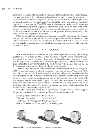
The following presents the simulation of field compaction conducted by Wang et al.
(2007) to provide a guide in identifying critical compaction factors. Wang et al. (2007)
used the porous viscoplasticity (Gurson-Tvergaard) model to study the effects of a few
influencing factors. The purpose of that study was to determine dominating factors and
to show whether modeling techniques can capture the essential compaction features. In
this compaction simulation model (Figure 11.12), the roller was assumed to be rigid and
the porous plasticity model was used for AC. Besides the constant loading applied on
the roller, a vibration force with a smaller magnitude was also applied on the roller. The
simulation was conducted using ABAQUS.
Using this model the effects due to compaction force, thickness, and soil support
factors were evaluated. The variables used for the simulations include:
Forces applied on the roller: 1F, 2F, 3F, 4F
Vibration of the roller: 0.02F*sin (62.8T)
Thickness of the AC section: 1.0t, 1.5t, 2.0t, 2.5t
Where F = 5000N, t = 30mm, and T is the loading time.
FIGURE 11.12 Finite element model for compaction simulation.