Page 389 - Mechanics of Asphalt Microstructure and Micromechanics
P. 389

Simulation of  Asphalt Compaction   381


                                                   15%
           15%
                                          1F
                                                                                   F
                                          2F
                                                   10%                             2F
           10%                            3F
          VVF                             4F       VVF                             3F
                                                                                   4F
                                                    5%
           5%
                                                    0%
           0%
                                                       0  1  2  3  4  5  6  7  8  9  10 11 12
              0  1  2  3  4  5  6  7  8  9 10 11 12
                           Passage                                  Passage
                                (a)                                                                   (b)
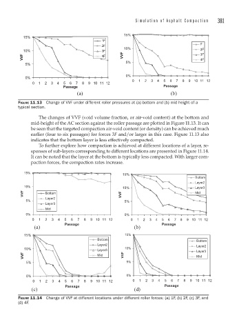
        FIGURE 11.13  Change of VVF under different roller pressures at (a) bottom and (b) mid height of a
        typical section.

                 The changes of VVF (void volume fraction, or air-void content) at the bottom and
              mid-height of the AC section against the roller passage are plotted in Figure 11.13. It can
              be seen that the targeted compaction air-void content (or density) can be achieved much
              earlier (four to six passages) for forces 3F and/or larger in this case. Figure 11.13 also
              indicates that the bottom layer is less effectively compacted.
                 To further explore how compaction is achieved at different locations of a layer, re-
              sponses of sub-layers corresponding to different locations are presented in Figure 11.14.
              It can be noted that the layer at the bottom is typically less compacted. With larger com-
              paction forces, the compaction rates increase.

           15%
                                                   15%
                                                                                Bottom
                                                                                Layer2
           10%
                                                   10%                          Layer3
          VVF       Bottom                        VVF                           Mid
                    Layer2
            5%                                      5%
                    Layer3
                    Mid
            0%                                      0%
              0  1  2  3  4  5  6  7  8  9 10 11 12   0  1  2  3  4  5  6  7  8  9 10 11 12
                           Passage                                 Passage
               (a)                                      (b)
           15%                                      15%
                                         Bottom                                  Bottom
                                         Layer2                                  Layer2
           10%                           Layer3     10%                          Layer3
           VVF                           Mid       VVF                           Mid
            5%                                       5%


            0%                                       0%
              0  1  2  3  4  5  6  7  8  9  10 11 12   0  1  2  3  4  5  6  7  8  9  10 11 12
                            Passage                                 Passage
              (c)                                       (d)
        FIGURE 11.14  Change of VVF at different locations under different roller forces: (a) 1F, (b) 2F, (c) 3F, and
        (d) 4F.
   384   385   386   387   388   389   390   391   392   393   394